
Description
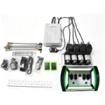
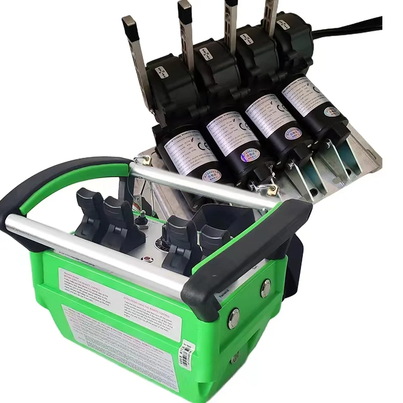
Hydraulic valve remote control converts a manually operated valve bank into a radio-controlled one without replacing the valve. A servo actuator is bolted onto each existing lever, the vehicle’s 12 V or 24 V supply drives it, and the joystick commands proportional travel in both directions — so valve opening follows stick position instead of being fixed by a contactor.
Because the actuator is an external mechanism, the hydraulic circuit is never opened. No oil is drained, no manifold is machined, and the manual lever stays functional, which is what makes the conversion practical on machines that are already in service rather than only on new builds.
■ How a hydraulic valve remote control works
The system replaces the operator’s hand, not the valve. Three elements do the work:
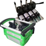
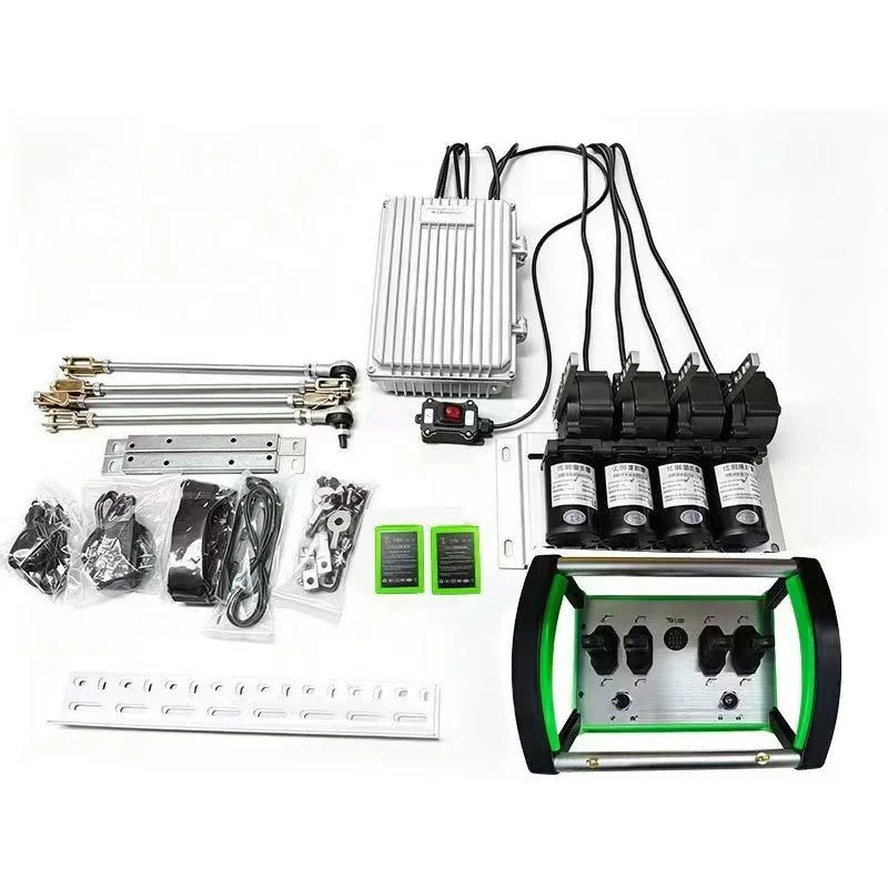
- The servo actuator is a motorised unit that grips the existing valve handle through its full travel. It is a proportional actuator, not a two-position one: the further the joystick moves, the further the handle is stroked, so a crane can be feathered instead of only run at one fixed speed.
- The receiver is mounted on the machine and converts the radio command into drive current for each actuator, one output per controlled valve section. It runs from the vehicle supply and is wired to the actuators with a harness rather than to the hydraulic system.
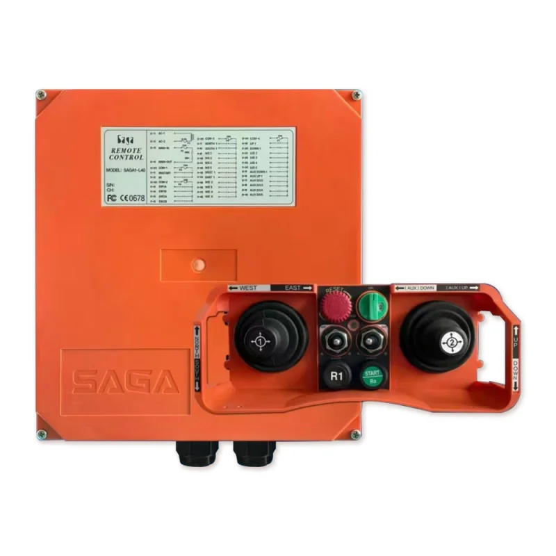
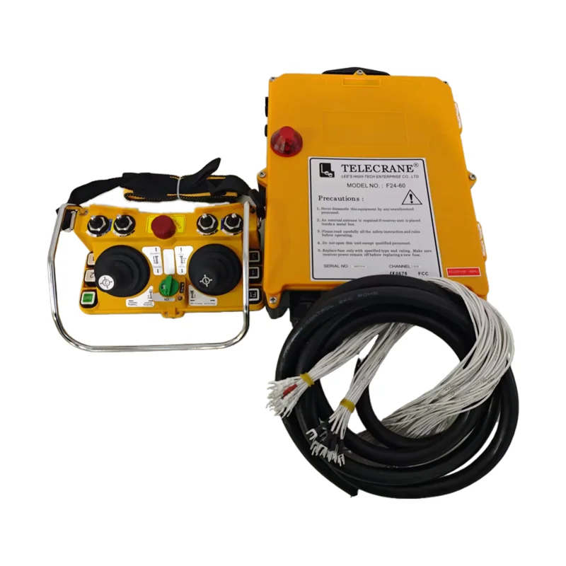
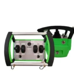
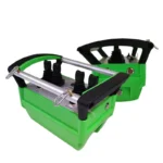
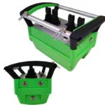
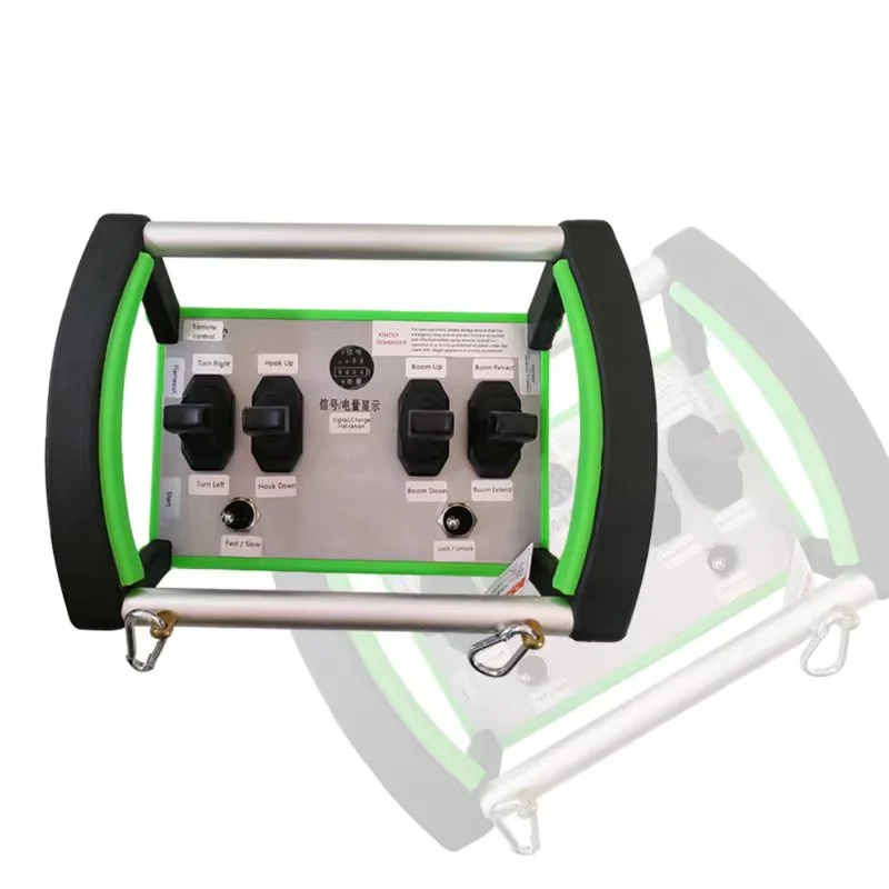
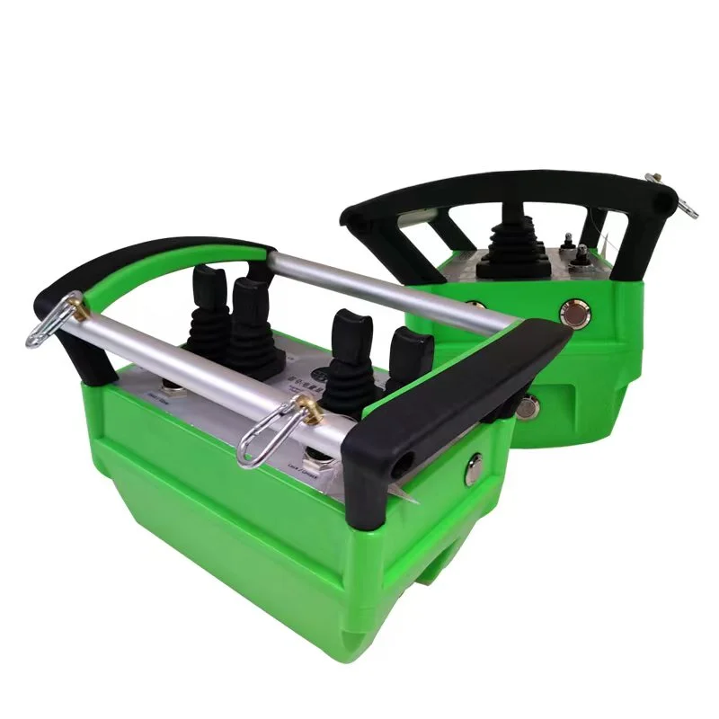
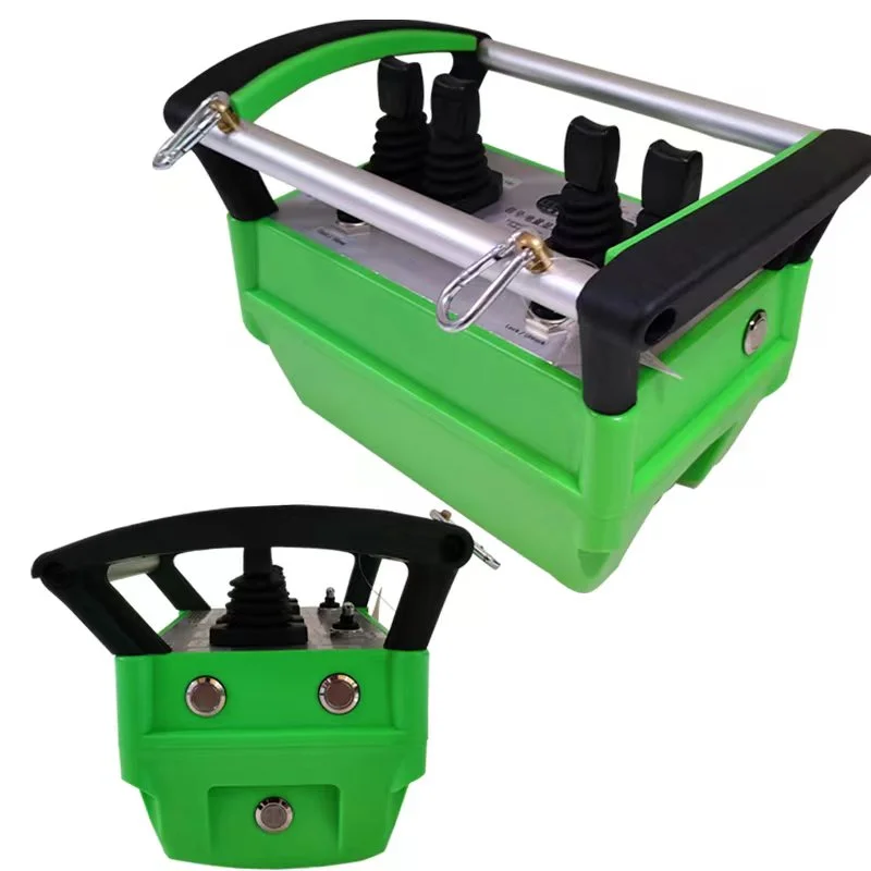
- The transmitter carries the joysticks, the start control and an emergency stop. Control channels are assigned per valve section, which is what the channel count refers to.
Because control is applied mechanically at the lever, the system suits machines whose valve bank was never built with solenoid coils — the common situation on older or mechanically controlled units.
■ Technical specification
| Product type | Wireless proportional servo-actuator kit for manual hydraulic valves |
| Valve compatibility | Manual lever valve banks — monoblock and sectional |
| Control channels | 4 channels standard; 2 / 4 / 6 / 8 available to order |
| Control mode | Proportional, with micro-adjustment and variable speed |
| Actuator mounting | Bolted at the existing valve handle position; manual operation retained |
| Actuator stroke | Matched to the valve handle travel and confirmed per valve at order |
| Supply voltage | DC 12 V / 24 V vehicle supply |
| Wireless range | 100 m to 500 m depending on configuration and site conditions |
| Frequency | 433 MHz RF radio link |
| Protection class | IP67 / IP68 on the outdoor-mounted assemblies |
| Emergency stop | Fitted on the transmitter |
| Transmitter material | High-strength nylon / engineering plastic |
| Actuator and backplate material | Reinforced metal |
Two of these rows carry more weight than the rest and are worth reading before the specification is treated as final: the channel count determines how many valve sections can be operated, and the actuator stroke has to match the handle travel of the specific valve, which is why a photograph and a measurement of the valve bank are part of the ordering process rather than an optional extra.
■ Matching the system to your valve architecture
Hydraulic valve remote control fails as a project when the actuator is chosen before the valve is understood. Five checks settle the specification.
- Identify the valve architecture first. A monoblock valve bank carries every section in one casting, with the levers grouped closely together; a sectional bank is a stack of individual slices with more space between levers. The two need different mounting hardware and different backplate arrangements, so the first photograph you send should show the whole bank rather than one lever.
- Decide proportional or on-off per function. Proportional actuation is what allows a boom to be feathered and a winch to be inched, and it is the reason to choose this system over a simple relay remote. On a machine where some functions only ever run fully open — an outrigger, a stabiliser leg, a locking pin — a proportional actuator adds cost without adding capability, and those functions can be left on manual control.
- Count the channels against the functions you will actually control. Four channels cover the usual main-boom set. Six and eight channel versions exist for machines with more sections or with two independent work functions. Because the receiver is built for the channel count ordered, this decision is cheaper to make once than to revisit later.
- Check that the actuator travel suits the valve. The actuator has to stroke the handle through the valve’s own full range, in both directions, without reaching the mechanical stop before the valve does. Send the handle travel, the mounting space around the lever bank and the valve make and model; that combination is what the stroke and mounting plate are confirmed against.
- Settle the electrical side. Confirm the vehicle supply voltage at the mounting position, and plan a dedicated feed for the receiver rather than sharing a circuit with the alternator or a two-way radio. Mobile electrical systems are electrically noisy and the receiver is the part most affected by a poor feed.
■ Price bands for a hydraulic valve remote control kit
Indicative export prices, ex-works Zhejiang, for a transmitter, receiver and proportional servo actuator set. They are a planning guide rather than a quotation, because the kit is built around the channel count and the valve it has to fit.
| Configuration | Indicative price (USD) |
| 2-channel proportional kit | 150 – 330 |
| 4-channel proportional kit (standard build) | 220 – 450 |
| 6-channel proportional kit | 300 – 620 |
| 8-channel proportional kit | 380 – 780 |
| Additional servo actuator, same specification | 55 – 140 |
| Spare transmitter | quoted per unit |
Channel count is the main driver, followed by whether the mounting plates are standard or have to be made for a particular valve bank. Quantity reduces the unit price on fleet orders, and adding an actuator or a spare transmitter to the original order costs less than buying them separately later, because the matching has already been done against your valve.
■ Ordering information, lead time and warranty
What to send with the enquiry
Valve make and model, whether the bank is monoblock or sectional, the valve handle travel and the mounting space around the lever bank, the number of sections to be controlled, the vehicle supply voltage, and the machine type. Photographs of the lever bank with a ruler visible in shot are more useful than a description, and for a fleet enquiry list each machine with its section count so the whole order can be built with consistent mounting hardware.
Lead time and delivery
Single kits are quoted from 1 set for evaluation. Typical lead time is 15–25 working days where standard mounting plates suit the valve, and 25–40 working days where plates have to be produced, or where a fleet order spans several machine types. Payment terms are issued with the quotation. Kits ship in export cartons with the harness, mounting hardware and manual included; actuators and spare transmitters travel in the same consignment when ordered together.
Warranty and technical support
Twelve-month warranty against manufacturing defects, covering the actuators, harness and mounting hardware under the same terms; items worn or damaged in service are excluded. Technical support covers mounting, harness routing and receiver configuration, and because the actuator specification is recorded against the order, a second machine can be added later using the same arrangement rather than being re-engineered from scratch.
■ Engineering background
Zhejiang iehc Electrical Technology Co., Ltd has manufactured electrical control equipment in Liushi Town, Yueqing, Zhejiang since 2003 — a 1,500 sqm plant with 50+ staff and 20+ sets of production and testing equipment, working as an integrated manufacturer with its own R&D, tooling and assembly. Six patents, twelve trademarks and thirteen qualification certificates sit behind the control product lines, and CE marking and an ISO quality system apply across the range.
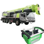
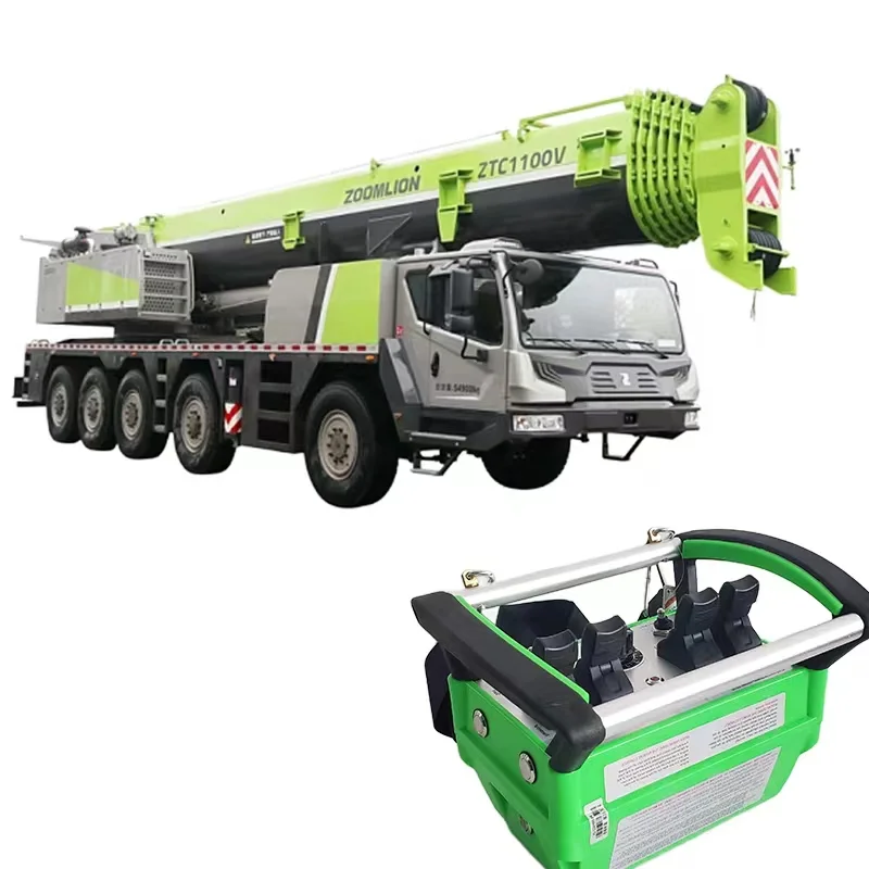
Retrofit mechanics sit in the custom side of the business, where the value is in the engineering step rather than the hardware alone: matching an actuator to a valve handle, producing a mounting plate that fits the bank as it actually is, and documenting the arrangement so it can be repeated across a fleet. That is the same approach used on the truck mounted crane wireless remote control system, which packages the same retrofit principle as a complete machine-level kit.
Other proportional and joystick-based systems are grouped under the joystick remote control range, and button-controlled systems for machines with solenoid valves under industrial remote control systems.
Send photographs of the valve bank with dimensions, the valve make and model, the sections to be controlled and the vehicle voltage through our contact page. We will confirm the actuator arrangement, the channel count and a firm price. Ordering, packing and payment questions are covered on the IEHC FAQ page.
FAQ
What is the difference between proportional and on-off control on a manual hydraulic valve?
On-off control drives the valve to one position: the function runs at the speed set by the valve and the operator cannot vary it. Proportional control moves the handle through intermediate positions, so the operator chooses the speed by how far the joystick is moved, and can feather a boom or inch a winch. Physically the difference is in the actuator and the receiver drive, not in the valve — the same valve handle produces either behaviour depending on what is bolted to it, and on most machines the proportional version is what makes the conversion worth doing.
Does the same actuator fit monoblock and sectional valve banks?
The actuator itself is common to both; the mounting hardware is not. Monoblock banks have their levers grouped tightly in one casting, which limits the space available for mounting plates, while sectional banks have more room between slices and often accept a simpler arrangement. This is why photographs and a measurement of the bank are requested before the kit is built. Where the space is unusually tight, a different backplate arrangement is produced rather than forcing the standard one into place.
How is the actuator stroke matched to the valve handle?
The actuator has to move the handle through the full travel the valve allows, in both directions, and stop before the mechanical end stop so the valve is not held against it. Handle travel is measured on the machine and the linkage is set to match at build, which is why the valve make and model and the measured travel are part of the order rather than an installation detail. On a machine with a short-throw lever, a longer linkage is used rather than a longer actuator.
How is the system wired and powered on the vehicle?
The receiver takes the vehicle's 12 V or 24 V DC supply and drives each actuator through the supplied harness; no connection is made to the hydraulic system at any point. Feed the receiver from a dedicated circuit with its own protection rather than from a shared accessory circuit — mobile electrical systems are noisy, and a receiver sharing a feed with a two-way radio or the alternator charging path is the most common cause of intermittent behaviour that gets blamed on the radio.
Can a machine with no existing electrical wiring be retrofitted?
Yes, and that is the case this system is designed for. Because the actuators are externally mounted and the only electrical work is a supply to the receiver and a harness to the actuators, a purely mechanical machine needs no valve replacement, no coil installation and no manifold work. The practical requirement is a 12 V or 24 V supply at the mounting position and enough space around the lever bank for the actuator bodies, both of which are confirmed from the photographs before the order is released.
Request Quote
Tell us your specifications, quantity, or application scenario and we will reply with a tailored quote.