Duty Cycle and Continuous Use in Crane Remote Controls
Duty cycle decides whether relays are a consumable or a lifetime part. How to count operations, and what that count changes in the order.
Read More

Pendant station wiring fails in the same three places on almost every job. The core count is ordered from the button count, the common conductor is borrowed from the emergency stop circuit, and the earth is landed on the nearest screw in the station body because it is within reach. Each is a small decision taken at the bench, and each produces a fault that someone else spends a shift tracing. The sequence below works from the functions backwards, so the cable is specified before it is cut and the stop circuit is kept separate from the control circuit from the start.
Each button contact needs its own core, so a single speed station takes one core per button and a double speed station takes two, because the second stage is a separate contact rather than a second signal on the same wire.
Add the common conductor, which is shared by every button contact, and then add the emergency stop pair. The stop is a separate circuit returning to the panel, so it takes two cores of its own and is never carried on the button common.
That gives a simple sum: buttons multiplied by stages, plus one common, plus two for the stop.
| Station | Buttons | Stages | Cores required | Cable to order |
|---|---|---|---|---|
| Single speed, hoist only | 2 | 1 | 5 | 6 core |
| Single speed, hoist and travel | 4 | 1 | 7 | 8 core |
| Single speed, three motions | 6 | 1 | 9 | 10 core |
| Double speed, hoist and travel | 4 | 2 | 11 | 12 core |
| Double speed, three motions | 6 | 2 | 15 | 16 core |
Order one size above the calculation where a horn, a light or a second function is even being discussed, and order from the button count alone never: that is what produces the classic complaint arriving with the station, enough cores for the buttons and none left for the stop.
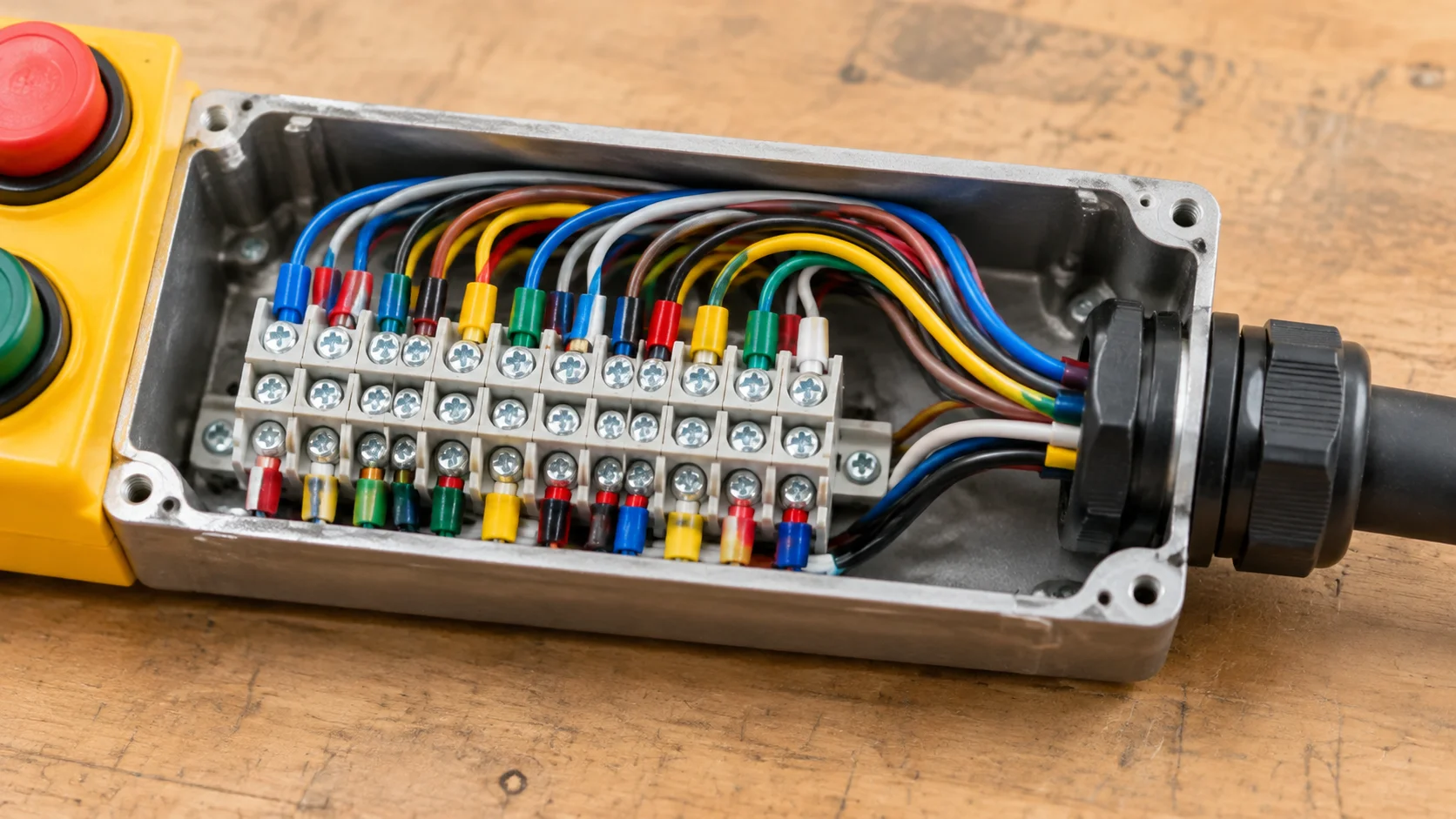
The common is a convenience, not a safety device. Every button contact closes onto it, and the return path to the panel is a single core. That is entirely acceptable for direction and hoist signals, and it is entirely unacceptable for the emergency stop, for one reason: a fault in the common can disable the stop at the same moment it disables the controls, and nobody notices until the day the stop is needed.
A separate stop pair returning to its own terminal means the stop circuit can break the main contactor coil independently of anything else in the cable. It also means a short to earth, a crushed core or a loose ferrule in the button common leaves the stop working, which is the correct failure direction. Where a station is supplied with a factory fitted stop block, the two contacts on that block are normally closed in series and should be wired as a loop, not referenced to the button common.
The distinction matters more as the station ages. A pendant control station that has been dropped, dragged and rained on will eventually have a chafed core, and the only question worth asking of the wiring design is whether that chafe disables the stop or merely disables a direction.
The COP-3MS single speed pendant and the COP-3MD double speed pendant are externally identical, which is exactly why they get mixed up on site. Internally the double speed button carries two contacts operated by one actuator: partial travel closes the slow contact, further travel opens it and closes the fast one, or closes a second contact alongside it depending on the mechanism. Either way the station has two terminals per direction where the single speed station has one.
That difference has to be met in the panel, not in the station. Two contactors per direction are needed, with an electrical interlock so the slow and fast coils cannot be energised together, and the changeover logic has to match the contact sequence the station actually produces. Wiring the station correctly and the panel logic wrongly gives a hoist with one speed only, or one that drops to slow whenever both contacts close. The mechanical difference between the two arrangements is described in single speed against dual speed hoist control.
The multi-button variants follow the same arithmetic. A COB-6 series station with eight buttons typically carries four directions at one or two stages plus a stop, so the terminal block grows faster than the enclosure does, and the core count grows with it.
The protective earth needs its own core, sized at least as large as the phase cores, landing on a machine screw in the metal frame with a shake-proof washer. It must not be the cable screen, and it must not be a spare core borrowed at the last minute, because both rely on a connection that is easy to leave loose and impossible to inspect once the gland is tightened.
The screen is a separate matter. Its job is to give interference a short path to earth rather than a route through the control cores, and it should be bonded at the panel end only on most installations. Bonding both ends is correct only when the station and the panel share a solid equipotential bond through the structure, otherwise the screen carries circulating current and becomes the fault it was meant to prevent. Where the station cable runs beside a variable frequency drive feed, the screen and the physical separation matter more than the core count.
A station that hangs on a cable also pulls on its own terminations, which is why the gland should grip the sheath rather than the cores.
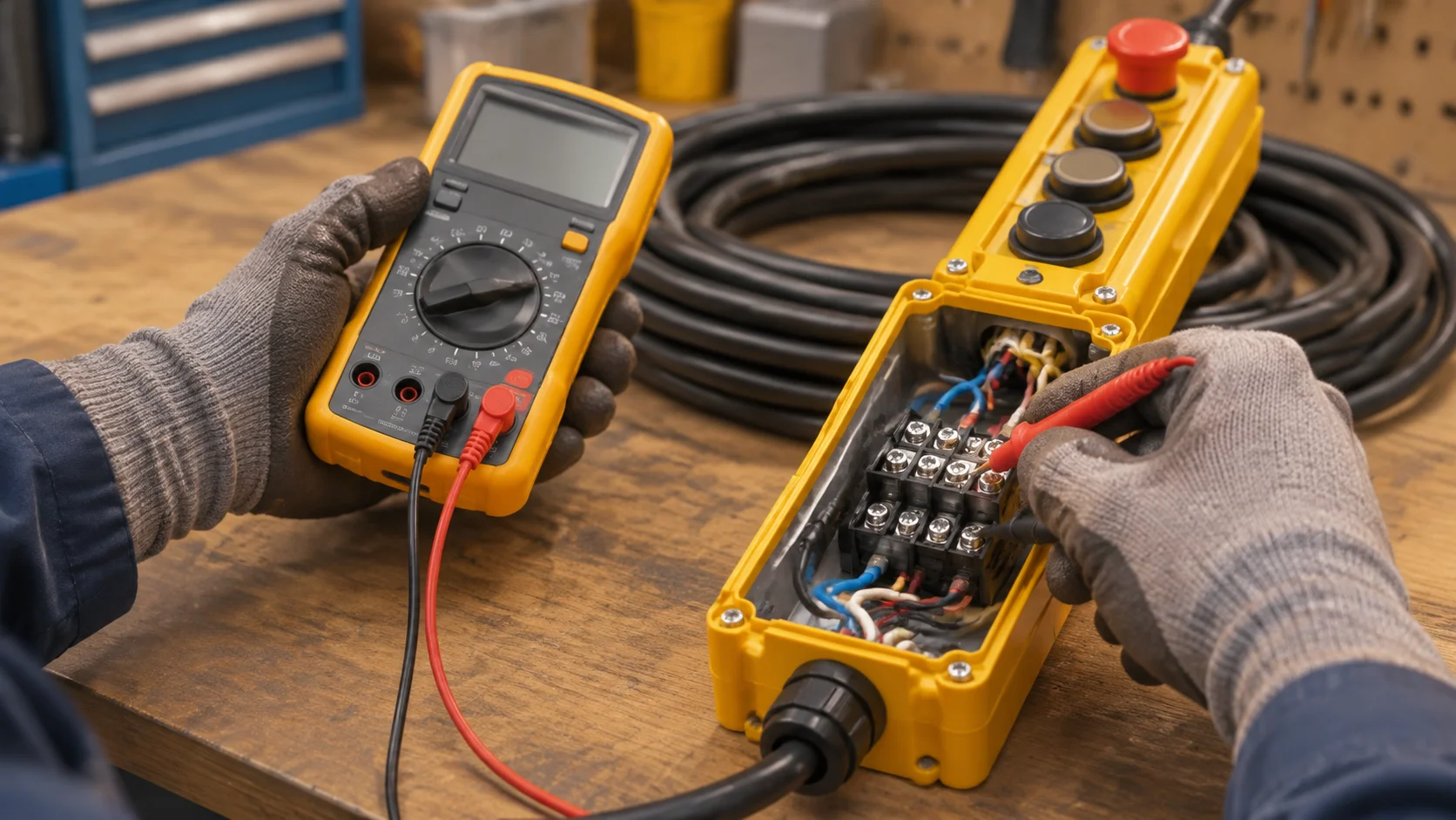
Each takes a minute with a meter and saves an hour of fault finding.
Only after all five should the panel be energised, and the first live test should be the stop, on an unloaded machine, before any direction is tried.
Most pendant faults that appear months after commissioning trace back to the bench rather than to the design. The three recurring ones are a ferrule that was twisted rather than crimped and slowly works loose under the vibration of every button press, a gland tightened onto the cores instead of the sheath so the conductors take the hanging load, and condensation where the gasket was seated on paint rather than bare metal.
A station with a proper terminal block and a separate stop pair can be tested in place in minutes, which is the practical argument for the extra two cores. When the single speed station is being chosen for a new crane, the wiring layout in the crane control wiring diagram is worth reviewing alongside the station drawing, because the two documents are usually drawn by different people and rarely agree on terminal numbering.
Where a station is being replaced on an existing crane, keep the old terminal schedule and photograph it before disconnecting anything. Stations are frequently rewired during their life, and the drawing in the panel is often two revisions behind. For a station supplied with a pre-fitted cable and a terminal schedule that matches it, send the button layout and voltage through the contact form and the core count can be confirmed against the panel before the order is placed.
Buttons multiplied by stages, plus one common, plus two for the emergency stop. A four button single speed station needs seven, so eight core cable is usual; a four button double speed station needs eleven, so twelve core.
No. A fault in the shared common can disable the stop at the same time as the controls. The stop needs its own pair returning to a separate terminal so it can break the contactor coil independently.
Usually at the panel end only. Both ends are acceptable where the station and panel are firmly bonded through the structure, but bonding both ends without that bond makes the screen carry circulating current.
Because the button operates two contacts in sequence, half travel for slow and full travel for fast. The panel needs two interlocked contactors per direction to use them.
No. The protective conductor must be a dedicated core, sized at least as large as the phase cores and landed on a machine screw with a shake-proof washer so the connection can be inspected.