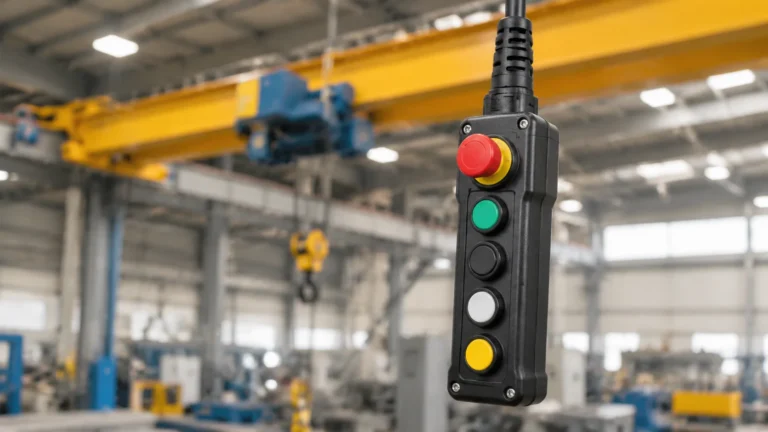
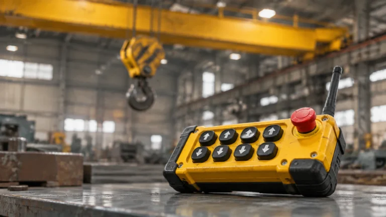
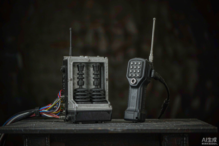
Pendant Control Station Wiring: Cores, Common, Earth
Cores follow functions, not buttons. The sum that sizes the cable, why the stop must not share the button common, and five pre-power checks.
Read More

A crane limit switch is a mechanical device that breaks the travel circuit before the machine reaches its physical stop, and the heavy-duty versions exist because ordinary lever switches do not survive the duty. The single decision that matters most is the actuator: a cross-link switch covers both end-of-track directions from one mounting point, where a lever switch covers one and needs a partner at the other end. Everything else — contact arrangement, rating, housing — follows from how the drive is supposed to stop.
This guide covers the selection parameters that actually matter on a crane travel drive, the difference between alternating and graded contacts, and the installation checks that decide whether the switch trips at the right point in two years’ time.
A cross-link actuator solves the geometry rather than the electronics. The actuator is a square cross — 6 mm on the XCKMR range — and because it presents the same profile from four directions, the mechanism trips it whichever way it arrives. One switch, one bracket, both directions, with the same switching action in each.
| Consideration | Cross-link actuator | Lever actuator |
|---|---|---|
| Directions covered per device | Both directions of travel from one mounting point | One direction; needs a second switch at the other end |
| Bracket complexity on a crane girder | One bracket and one cable run | Two brackets, two cable runs, two terminal entries |
| Slow-down plus stop sequencing | Straightforward — the cross can trip staged contacts in sequence | Possible, but sequencing depends on strike position and lever travel |
| Best fit | Crane long travel, cross travel, hoist end stops, hatch and door travel | Tight spaces, single-direction guards, machines where the switch must be struck by a dedicated dog |
| Setup risk | Cross must be square to the striking dog in both axes | Lever angle and over-travel must be set within a narrow band |
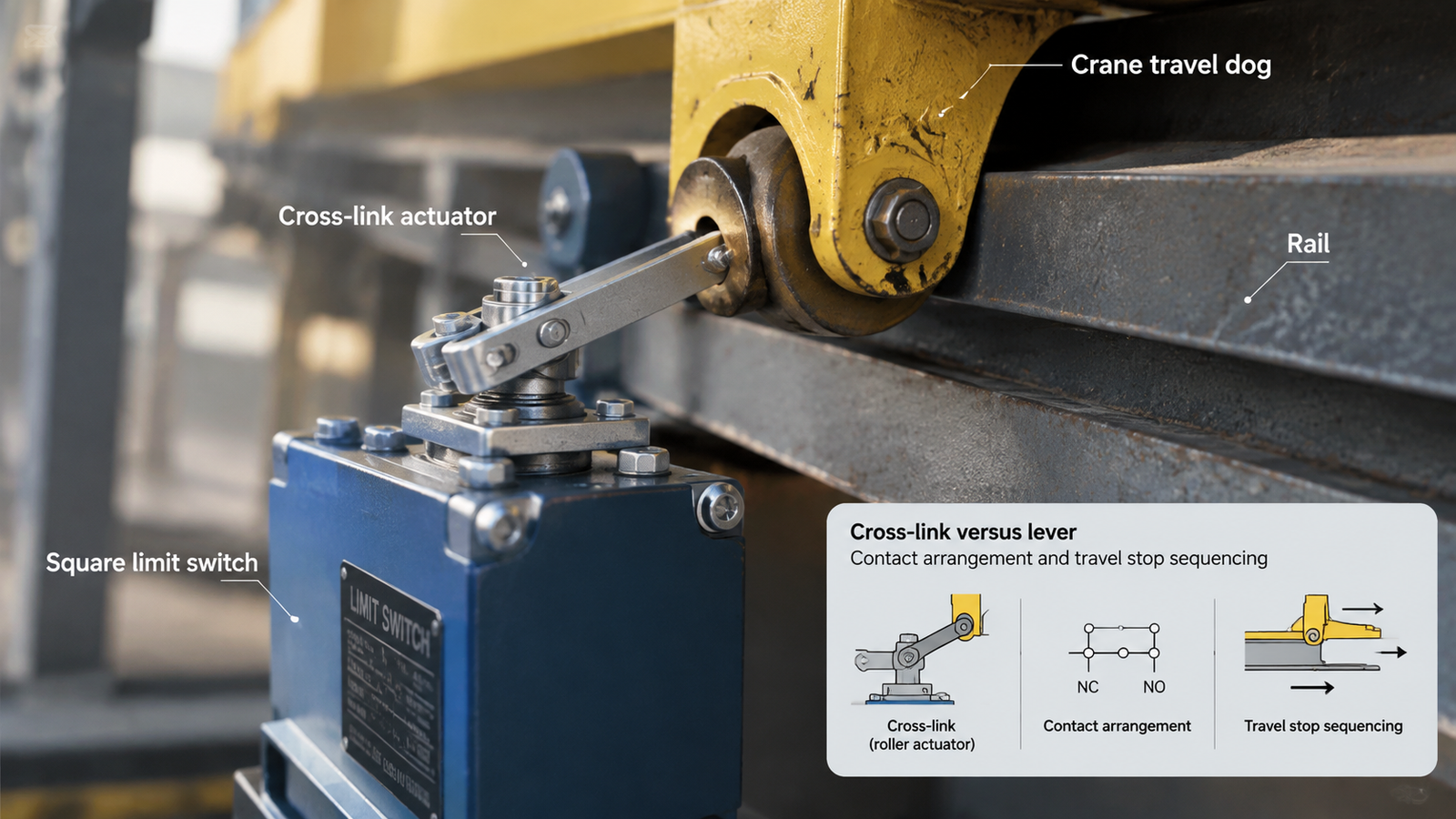
This is the part buyers most often leave to the supplier, and it is the part that determines whether the crane stops in one step or two. Heavy-duty cross switches are commonly supplied with four contacts arranged as two two-pole groups, and the two groups can be wired to act together or in sequence.
| Arrangement | How the contacts act | When to specify it |
|---|---|---|
| Simultaneous | Both pairs open at the same point in the actuator stroke | Simple end stop where the drive can be cut directly and the load is not at risk of swing |
| Graded (staged) | First pair operates early in the stroke, second pair later | Where the drive must slow before it stops — long travel at speed, heavy loads, high-inertia mechanisms |
| Alternating | Pairs assigned to different functions on the same travel | Where one switch must separate a slow-down circuit from a run circuit, or a run circuit from a brake release |
| Parameter | What to check | Why it matters on a crane |
|---|---|---|
| Housing material | Metal, typically a zinc alloy such as Zamak, rather than moulded plastic | Survives impact from a swinging load or a maintenance trolley without cracking |
| Impact rating | IK code, for example IK07 | A switch that breaks on impact is a switch that stops protecting the machine |
| Ingress protection | IP66 for dusty and humid plant, outdoor girder positions | Dust-tight plus jet-resistant; note it is not an immersion rating |
| Insulation voltage | Ui 500 V | Margin above the control-circuit voltage actually used |
| Operational current | 3 A at 240 V AC-15 | Adequate for relay and contactor coils, not for motor circuits |
| Mechanical life | 2,000,000 operations | The device may be tripped on every cycle in some duty patterns |
| Temperature range | −25 °C to +70 °C | Covers unheated outdoor girders and hot plant areas |
| Cable entries | Three M20 × 1.5 outlets | Lets in and out cables be separated when several switches are daisy-chained |

The limit switch shares its panel with the devices that actually switch the drive — rotary isolators, cam changeover switches and foot pedals — which sit together under control switches.
A limit switch is the last line of protection on a travel drive, and it must work the same way regardless of which control point is in command. That is easy with a pendant on a fixed cable and less obvious once a radio system is fitted, because the receiver’s relays are in series with the panel circuit and their behaviour on a lost signal has to be understood.
Most industrial remote control receivers drop their outputs when the link is lost, which means the travel contactor opens and the drive coasts to a stop wherever it is. That is the intended behaviour and it is not a limit switch function. What the two systems must share is the stop circuit: the emergency stop path, the limit switch path and the receiver’s own stop output should all be visible on one drawing so that a fault in any of them can be traced without dismantling the panel.
For the electrical side of the panel — isolators, changeover switches and the auxiliary devices that sit alongside the limit switch — the electrical equipment and supplies range covers the same duty class. Where the travel run needs a second switch at the opposite end rather than a cross-link unit, the crossbar rotating-head limit switch provides four-way lever operation with up, down, left and right travel limiting, and is the simpler fit where the mechanism already has dogs on both sides.
Choose the actuator for the geometry, choose the contact arrangement for the way the drive must stop, and install the switch so that the dog sets the trip point on a rigid bracket. A heavy-duty housing buys you time against impact and weather; it does not buy you a correct setting. The XCKMR heavy-duty cross limit switch covers the crane travel duty described here, and the specification sheet is the place to confirm rating and contact configuration against your panel.
If you are specifying travel protection for a new crane or replacing switches on an existing run, send the travel speed, the control-circuit voltage and the required stop sequence through the contact form and the contact arrangement can be checked before the order is placed.
The end stop is the mechanical buffer that physically prevents over-travel. The limit switch is an electrical device that opens the control circuit before the mechanism reaches that buffer. A crane needs both; the switch protects the machine from the shock of hitting the stop, and the stop protects it if the switch fails.
Yes, if it has a four-way cross-link actuator. The cross presents the same profile from either direction, so the mechanism trips it approaching from the left or the right. A lever switch covers one direction only and needs a second unit at the other end.
No. It should break the contactor coil circuit. The contacts on a heavy-duty cross switch are rated for control duty — 3 A at 240 V AC-15 on the XCKMR range — and are not sized to interrupt motor current. Used on a motor circuit, the contacts will weld and the crane will lose its end stop.
The two contact pairs operate at different points in the actuator stroke. The first pair can trigger a slow-down and the second can break the run circuit, so the drive decelerates before it stops. That reduces load swing and wear on the brake compared with a single-step stop.
Test the trip function at every planned inspection and at least monthly on a crane in daily use, from each control point including the radio transmitter. Check the actuator for wear and the bracket for movement at the same time, since a switch that has shifted trips at a different point without any fault in the switch itself.