Pendant Control Station vs Radio Remote Control: Which Fits?
Pendant control station or radio remote control? Compare cost, safety, operating range and maintenance, see which fits your working conditions, and plan a hybrid setup.
Read More
A crane remote control wiring diagram looks intimidating because every terminal is drawn at once. Read it in blocks and it becomes simple: the receiver has a supply side, a common terminal, a set of relay outputs, and a safety circuit. Once you can separate those four groups, receiver output wiring and fault tracing stop being guesswork.
The single most important idea behind any crane remote control diagram is that the output is a switch, not a power source. Everything that follows in this guide builds on that one point.
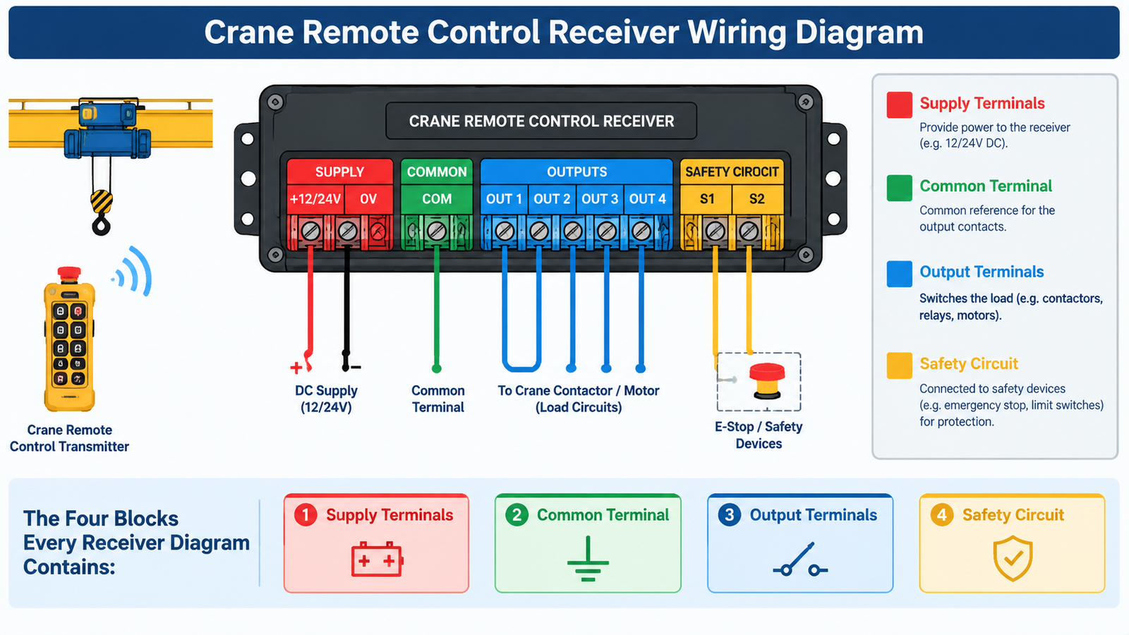
Manufacturers draw diagrams differently, but the electrical content is nearly always the same four groups. Identify them before you read anything else.
| Block | What it is | What to verify |
|---|---|---|
| Supply terminals | The receiver’s own power input | Voltage and type match the machine supply; DC polarity observed where marked |
| Common terminal | A shared reference terminal for the output contacts, often labelled COM | Which outputs share it and whether more than one common group exists |
| Output terminals | Relay contacts, one pair per function, shown as normally open or normally closed | Which physical output corresponds to which motion and to which speed stage |
| Safety circuit | Emergency stop output, and on some models a start or enable output | Where the stop circuit terminates in the panel and how it is reset |
Diagrams usually carry a wire colour legend beside the terminal numbering. Colours are manufacturer-specific and sometimes change between production runs, so read the legend that came with your unit rather than assuming a colour from a previous installation.
This is where the majority of installation damage happens. Receiver outputs are potential-free relay contacts. Each output pair behaves like the two ends of a switch that the transmitter closes and opens. The receiver does not feed voltage into the contactor coil — the machine’s own control circuit does.
Two consequences follow directly from that:
Read the common group carefully. Systems with many outputs sometimes split them across more than one common terminal, which lets you switch different functions from different circuits. If your diagram shows two common terminals, treat them as two separate groups and trace each output back to its own common.
Speed stages change how many outputs each direction consumes, and this is the part that most often causes a mismatch between an ordered transmitter and the machine it is intended for.
| Aspect | Single-speed | Double-speed |
|---|---|---|
| Outputs per direction | One | Two, typically a slow and a fast stage |
| Contactor arrangement | One contactor per direction | Two contactors per direction, with mechanical or electrical interlocking between stages |
| Transmitter button behaviour | Press for motion, release to stop | First stage engages on a partial press, second stage on a full press |
| Typical machine | Single-girder crane or hoist with fixed travel speed | Crane with fast and slow travel, or a hoist with inching control |
| Wiring risk | Low | Both speed outputs for one direction must never be energised at the same time |
A transmitter configured for single-speed operation cannot drive a double-speed machine without losing the second stage, and a double-speed transmitter driving a single-speed machine leaves outputs unused. Count the outputs in the diagram before you count buttons on the transmitter: that number, not the button count, tells you what the machine actually needs.
The diagram will state the receiver’s rated supply, not the control voltage of the machine’s contactor circuit. Those are two different things and both matter. The table below shows the ranges you will meet most often.
| Typical supply | Where it appears | Notes |
|---|---|---|
| AC/DC 24 V | Modern panels with a control transformer or DC control supply | Observe polarity on DC supplies; the receiver power indicator stays off if reversed |
| AC 48 V and AC 36 V | Older panels and some hoist control circuits | Often available as an option rather than as standard |
| AC 220 V | Single-phase control circuits | Common on small hoists and light cranes |
| AC 380 V | Three-phase industrial supplies | The standard receiver voltage on many crane systems |
| Wide voltage band | Multi-voltage receivers used across mixed sites | Removes the need for an extra transformer but still needs the range confirming |
Wide voltage designs are increasingly common. The F24-12S/12D remote controller accepts AC 36 V, 48 V, 220 V and 380 V or DC 12 V and 24 V, with low and high operating bands covering roughly 18–65 V and 65–440 V AC/DC. Systems built around the remote control system for industrial cranes take a similar wide-voltage approach at 65–440 V AC/DC. Even with a wide-range receiver, record the actual measured supply in your commissioning notes, because a reading outside the intended band tells you the panel has a problem of its own.
For a transmitter with a defined button set, confirm the pairing between button legends and outputs on paper before commissioning. On the F21-E1B industrial wireless remote control, the transmitter carries one start button, one stop button and six single-speed direction buttons, so six direction outputs plus the safety path is the wiring you should expect to find in the diagram.
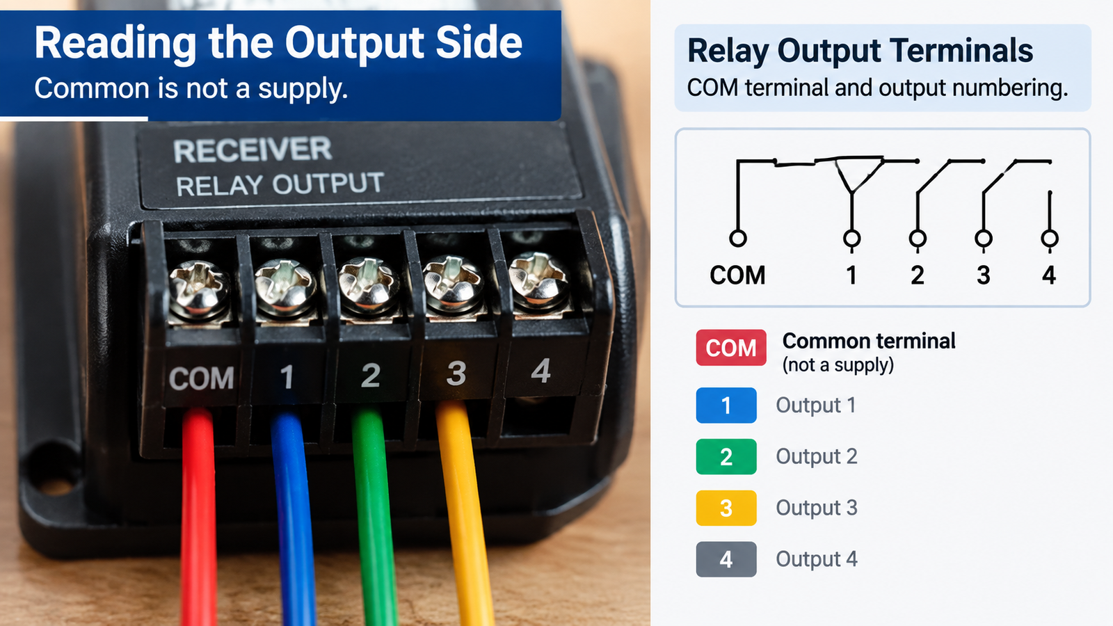
Once you know which output drives which motion, the diagram becomes a troubleshooting map rather than a puzzle.
Wire only with the diagram that came with your own unit, keep it in the panel after commissioning, and record the measured supply voltage, the output map and the date. The next person to open that panel will use that note far more than the original drawing.
If the diagram is missing, our engineers can help you map an unknown receiver from clear photographs of the nameplate and terminal block. Send the machine type, the number of motions, the speed stages and the supply voltage, and we will confirm which configuration matches your panel.
COM is the common terminal for the receiver’s relay outputs. Each output terminal forms a switch with the common terminal, so the two belong to the same circuit. The receiver does not supply the control voltage itself.
Because the outputs are potential-free contacts, the circuit they switch can in principle be separate from the receiver supply. In practice you must follow the diagram exactly: if the diagram shows one common group shared by all outputs, every output must switch the same circuit.
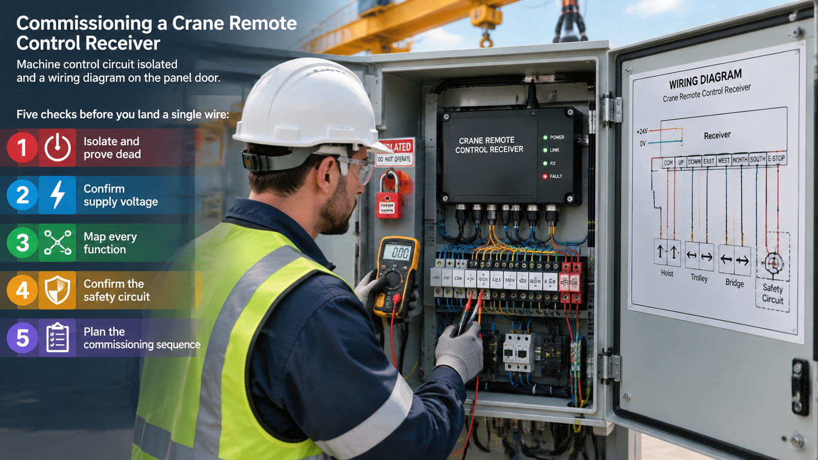
Test one output at a time with the machine circuit isolated, using a meter to identify which terminal closes when each button is pressed, then map the results to the machine’s motion list. Photograph the terminal block before you start so the original arrangement can be restored.
Most often the supply is absent at the terminal, a fuse has blown, or a DC supply has been connected with reversed polarity. Disconnect immediately if polarity is suspect, correct the connection and re-check before applying power again.
Not always. Single-voltage receivers need a matching supply, while wide voltage receivers accept a broad range and often remove the need for an additional transformer. Confirm the receiver’s rated band against the measured voltage in your panel before deciding.