Pendant Control Station Wiring: Cores, Common, Earth
Cores follow functions, not buttons. The sum that sizes the cable, why the stop must not share the button common, and five pre-power checks.
Read More

Ask how a radio remote control works and most answers start at the antenna, which is the least interesting part. The interesting part is that a single button press has to survive six separate conversions before a contactor closes, and every failure mode an operator will ever meet lives in one of those six. Understanding the chain also explains why a handset cannot simply be swapped for another brand, why the response feels sluggish on some machines, and why a two speed hoist needs hardware that a single speed one does not.
The chain is short but each link is a distinct piece of engineering.
The last step is the one worth repeating: the handset does not drive the motor. It closes a small dry contact, and the contactor does the work. All the current a radio receiver handles is coil current, a few volt-amperes, which is why the same handset family suits a 0.5 tonne hoist and a 20 tonne one.
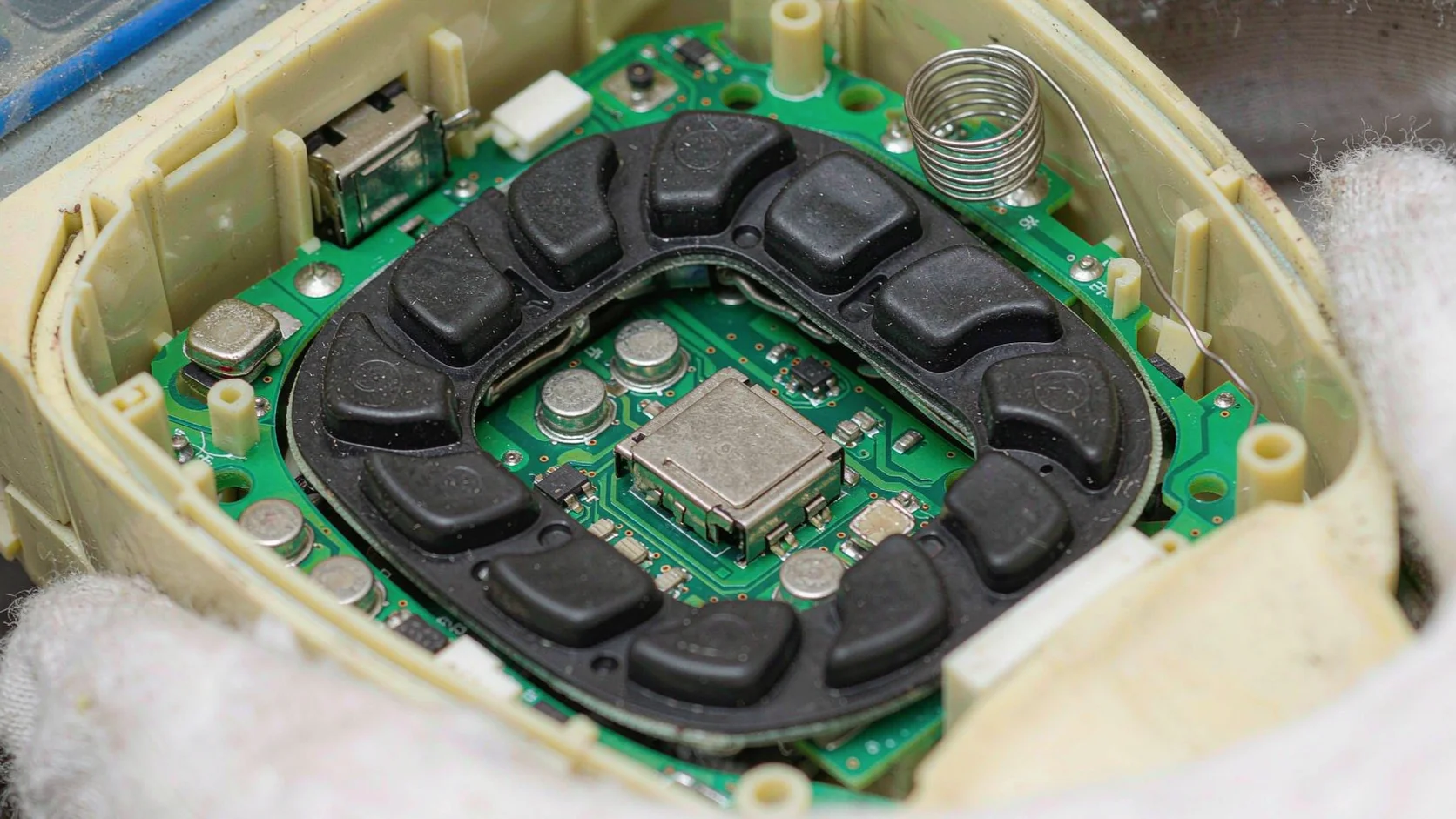
A radio link in a workshop full of cranes cannot simply transmit “hoist up”. Every receiver in range would act on it. So the data word carries an address, and the receiver acts only on words that carry its own.
Older systems stored that address in a bank of DIP switches, and the address was fixed, which meant two handsets set the same way were interchangeable and a neighbour’s handset could in principle drive your crane. Current systems generate a 32-bit identity in firmware and pair it once, so the receiver learns the address rather than reading it from a switch. Combined with a hopping pattern and a check code, the probability of a random match becomes negligible, which is exactly what the pairing procedure exists to guarantee.
This is also the answer to a question that comes up weekly: a handset from another maker will not work with your receiver, however identical it looks. The radio may overlap and the buttons may match, but the address and the word structure are proprietary. Replacement handsets work because they are programmed to the same protocol and then paired to the receiver, not because the hardware is the same.
Radio cannot send a continuous voltage, so “button held” is not a state on the wire. It is a stream: the transmitter repeats the same data word many times a second for as long as the button is down, and the receiver treats the arrival of repeated valid words as a held command. When the repeats stop, the output opens.
That design has two consequences worth knowing. The refresh rate sets how quickly the receiver notices a release, and the number of missed words the receiver tolerates before it drops all outputs sets the failsafe. A receiver configured to drop outputs after three missing words reacts faster but may chatter in a noisy environment; one that waits for ten is steadier but slower to stop. Neither is wrong, but the setting belongs in the machine file.
It also explains an intermittent fault that looks like a button problem. If one input closes physically but the board does not read it, the handset transmits a stream with that bit clear, and the machine behaves as though nobody is pressing anything. The radio is working perfectly, which is why the fault is easy to misdiagnose from the outside. A wiring diagram for the panel side helps you separate a dead input from a dead output.
Published response times of 30 to 100 milliseconds are achievable, and machines that feel sluggish are rarely limited by the radio. The delay is distributed across the whole chain.
Scanning and encoding cost a few milliseconds. The radio frame itself takes a few more, and the channel hopping adds a small variable on top. Decoding and relay operation add perhaps ten. Then the contactor coil has to build flux and pull in, which is the largest single term at 20 to 40 milliseconds in a large contactor, and the motor has to accelerate. Two thirds of the perceived lag can sit downstream of the receiver, which is why response time figures should always be read with the measurement point stated.
A machine that jogs well and creeps badly is usually showing contactor behaviour rather than radio latency. Replacing the handset to fix it rarely helps, and measuring at the coil is the way to prove where the time went.
On a single speed hoist, each direction needs one relay: hoist and lower, two outputs for one axis. Two speed changes the arithmetic, because slow and fast are physically different contactor combinations, not one contactor asked to hurry.
A two speed motor has two windings or a tapped winding, so the panel needs a contactor set for the low speed and another for the high speed, with an interlock so both cannot close together. The transmitter reflects that: a two step button, where a half press sends the low speed command and a full press sends the high speed command, so the same key covers both. The receiver therefore needs two outputs per direction instead of one, and a four motion two speed crane moves from eight outputs to sixteen.
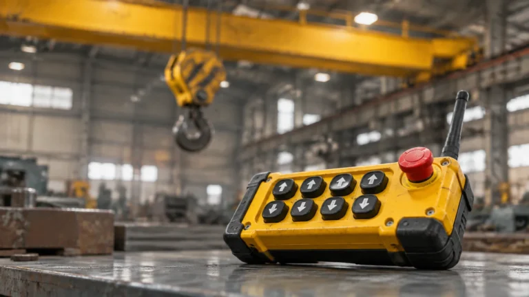
That is the whole reason the same yellow handset exists in single and dual speed versions with the same button count. The difference is in the PCB, the receiver relay count and the panel, not in the look of the transmitter. Specify the speed version at order time, because it is set by the hardware and firmware rather than by a menu an engineer can change later.
The vocabulary around these systems is inconsistent between suppliers, so here is the working set.
| Term | What it actually means |
|---|---|
| Transmitter | The handset. Encodes inputs and sends them; it switches no load. |
| Receiver | The box on the crane. Decodes, verifies identity, closes output relays. |
| Relay output | A dry contact closure, rated in amps at a stated voltage, not a motor rating. |
| Momentary | Output follows the button and opens on release. The default for crane motion. |
| Pairing | Teaching the receiver one transmitter identity. Not the same as matching frequency. |
| Duty cycle | How long the transmitter may transmit before the thermal limit applies. |
Four corrections follow from that table. The handset does not drive the motor, it commands a contactor. Range on a datasheet is open air, not through a steel structure. A receiver with a higher relay rating does not make a bigger crane work, because the contactor does the switching. And pairing is not a repair for a broken power supply, though it is often attempted as one.
The F24-6S and F24-6D system shows the chain in its simplest useful form: six button positions, six relays plus an independent emergency stop output, and 5 A contacts that switch contactor coils rather than motors. The 6S is single speed and the 6D is dual speed, using the same shell and the same pairing procedure, which is why the two are so often confused. Pairing and output behaviour are the two settings to confirm before a panel is wired, and the frequency band decides how the link behaves in a crowded plant. Send the panel drawing and the desired function list through the contact form and the output count can be confirmed against the drawing rather than guessed.
The transmitter encodes the pressed button into a data word carrying its identity, sends it by radio, and the receiver checks the identity and closes a relay. That relay energises a contactor, which starts the motor.
No. It switches contactor coils through small relay contacts. The contactor carries motor current, which is why a 5 A relay output can control a crane of any size.
Because the address and data format are proprietary even when the frequency and button layout match. A replacement must use the same protocol and then be paired to the receiver.
Most of it is downstream of the radio: contactor pull-in takes 20 to 40 milliseconds and motor acceleration more. Encoding, transmission and decoding together account for only tens of milliseconds.
Slow and fast are separate contactor combinations, so each direction needs two outputs instead of one. A four motion two speed crane uses sixteen outputs where a single speed uses eight.