Pendant Control Station Wiring: Cores, Common, Earth
Cores follow functions, not buttons. The sum that sizes the cable, why the stop must not share the button common, and five pre-power checks.
Read More

A crane remote control that refuses to move the crane is usually not broken. It is reporting something, and the transmitter and receiver carry that report in a handful of small LEDs. The difficulty is that the report is written in a private language. One maker blinks twice for a pairing fault and another blinks twice for a flat battery, and the leaflet that once explained the difference went into a drawer with the panel drawing. Here is how to read those lights in a way that holds across brands, and where to look when every light seems perfect.
Status LEDs are the cheapest diagnostic channel a manufacturer can fit, and every factory has fitted a different one. There is no equivalent of the OBD standard for a radio remote, so the codes were written by whoever wrote the firmware. Three things vary: the number of lamps, since some models multiplex everything onto a single colour-changing LED; the cadence, so a 0.3 second pulse may mean nothing on another brand; and the placement, with the transmitter lamp visible above the buttons while the receiver lamp sits inside a sealed enclosure.
What transfers between brands is the sequence: power, then idle, then link, then command. A receiver with supply and no link behaves differently from one with a live link, and that single distinction answers most field calls before anyone opens a manual.
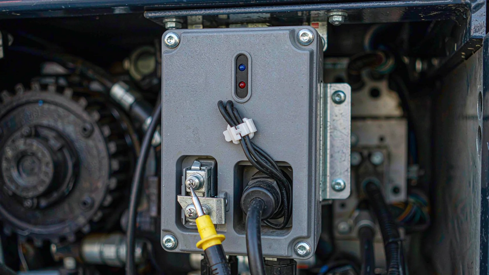
Before counting blinks, decide which of five states the lamp is in. Almost every code table is a subdivision of these.
Supply. A steady lamp after the isolator closes means the receiver has power. No lamp at all is not a radio problem, so check the fuse, the terminals and the transformer tap first.
Idle. A dim lamp or slow pulse with the handset off means the receiver is alive and has no valid link. This is correct behaviour and the most misread state on the machine, because a bright lamp looks like readiness to whoever stands in front of the panel.
Link established. A solid lamp, or a paired double pulse, once the transmitter is on confirms the address was accepted. If the lamp changes as the handset switches on, the radio side works and any remaining fault is downstream.
Low battery. A short blink at the transmitter when a button is pressed is a battery warning, not a command acknowledgement. On a 4 x AA handset it can appear before the machine stops responding.
Fault. Fast continuous blinking, or two colours alternating, is the only state that means open the manual. Colour alone will mislead you, because green is standby on one series and healthy on another. Read colour and rhythm together.
A blink code is a rhythm, not a total. Count the pulses inside one group and note the gap that ends it, because the gap separates a code of two from a repeat of one.
Two pulses followed by a pause usually points at the identity layer, meaning the address the receiver expects and the address the handset sends do not match. Three usually points at an output layer, where a relay is commanded and the feedback contact disagrees. Four commonly means a supply outside the accepted window, which a meter confirms in seconds. A continuous flicker with no rhythm is a hardware fault and no amount of re-pairing will clear it.
Counting by eye under pressure is unreliable, so use the phone in your pocket. Record a slow-motion clip at 120 frames per second and step through it. A pulse that looks instantaneous is three or four frames, and the pattern that seemed random resolves into a clean group you can send a supplier alongside the serial number.
On the receiver the lamp is often behind a sealed lid. Open it only with the supply isolated, and photograph the board before touching anything, because a gasket opened twice by hand rarely keeps its IP65 rating.

This is the most common callout and the least likely to be a radio fault. Work down the chain and stop where the signal disappears.
First, listen. A relay that clicks when a button is pressed proves the link, the decoding and the output driver are alive, which moves the problem into the panel. No click means nothing was commanded, so check the output configuration before suspecting hardware: a receiver set for maintained outputs behaves differently from a momentary one, and a handset paired to the wrong address shows a healthy link while sending commands nobody acts on.
Second, measure the contact. With the relay closed, the output terminal should show continuity across the common. If it does, the radio has done its job.
Third, follow the chain no remote control can see: contactor coil supply, the emergency stop string, the limit switch for the direction being commanded, the gate interlock and the panel isolator. A crane that travels one way but not the other is almost never a radio fault, because a radio fault removes both directions at once.
If the relay never clicks in any function, treat it as supply or pairing and test the receiver on the bench, which is faster and safer than testing a live crane. The bench test procedure takes twenty minutes with a multimeter, and why a crane remote control stops working covers the failures that only appear under load.
One rule is not negotiable: never test an output by bridging the emergency stop string. The stop circuit is the only part of the system that works when everything else has failed.
Remote control hardware is revised quietly. A receiver keeps the same model number for a decade while the firmware behind it changes three times, and the LED table usually follows the firmware rather than the model. A printed sheet from 2019 will confidently explain a pattern that no longer exists.
Two things identify the version. The label carries a date code or revision letter, and many receivers display their firmware at power-up with a short pattern in the first two seconds. Photograph both and keep them in the maintenance file beside the wiring drawing, because that pair is specific to the unit actually installed.
When you ask for a code table, quote the serial rather than the model. A supplier who replies with a model-level PDF has answered a different question, and it will be wrong in exactly the cases where you need it.
The table compresses the diagnostic order into something usable at the machine, without a laptop and without opening an enclosure.
| Symptom | Most likely stage | First check |
|---|---|---|
| No lamp on the receiver | Supply | Fuse, terminals, transformer tap |
| Receiver dim or pulsing, handset on | Link or pairing | Address match, second handset left on |
| Link steady, relay clicks, motor dead | Panel, not radio | Coil supply, stop string, limit |
| Two blink groups repeating | Identity or supply | Re-pair, then measure supply |
| Continuous fast flicker | Receiver hardware | Replace or return the module |
Whatever the outcome, record it. A fault that is logged becomes a pattern, and a pattern becomes a maintenance interval rather than an emergency.
Battery warnings deserve their own line in that log, because a handset that blinks for low cells behaves normally for one more shift and then fails at a bad moment. Drain that keeps returning points at charging practice rather than at the cells, as set out in battery drain.
The F24-6S and F24-6D system ships with a code table matched to its serial, and re-pairing is a two minute job rather than a service visit. Send the serial, the blink pattern and the measured supply voltage through the contact form and the answer can be specific to the unit instead of the model.
They report one of five states: supply present, idle with no link, link established, low transmitter battery, or a fault. The rhythm inside the fault state is brand specific and needs the code table for that serial.
A blink only proves the link and the decoding are alive. If the receiver relay clicks when a button is pressed, the fault is downstream in the contactor, stop string or limit circuit.
Record a slow-motion clip at 120 frames per second and step through it. Count pulses inside one group and note the gap that ends it, because the gap distinguishes a repeated single pulse from a code of two.
Yes. As the cells sag under transmit load the receiver may reject commands and report a link or identity fault. Fit fresh cells before diagnosing anything else.
Often on a label inside the transmitter battery compartment, and always from the supplier if you quote the serial. Model level tables go out of date when the firmware is revised.