Pendant Control Station vs Radio Remote Control: Which Fits?
Pendant control station or radio remote control? Compare cost, safety, operating range and maintenance, see which fits your working conditions, and plan a hybrid setup.
Read More
Crane remote control not working? The cause is usually simple: a discharged battery, a latched emergency stop, a blown output fuse or a lost radio link — and it can be found on site in a few minutes. What matters is the order in which you check, because a random search wastes time and can push you into the electrical panel before you have ruled out the simple causes.
This checklist works through crane remote control troubleshooting in five layers, starting with the checks that cost nothing and finishing with the ones that need a multimeter and an isolation permit.
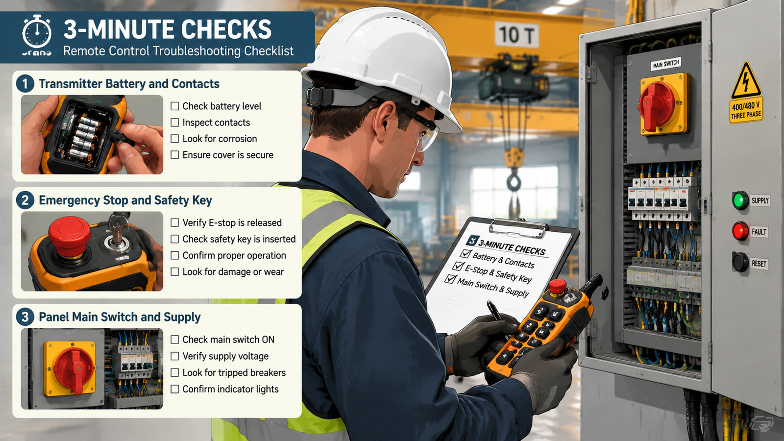
Before opening anything, confirm these three items. On a large share of call-outs the crane starts working again at this point.
Watch what the transmitter indicators do. A lit power indicator that still refuses to transmit points at the enable sequence or the safety key, not the battery.
Radio remote systems have five places where a command can be lost: the transmitter, the receiver supply, the radio link, the receiver outputs, and the machine circuit beyond them. Each layer has its own symptoms, so the table below maps them.
| Layer | Typical symptom | Likely cause | Action |
|---|---|---|---|
| 1. Transmitter and power | No indicator, or indicator on but nothing transmits | Flat battery, contaminated contacts, key not inserted, stop latched | Replace cells, clean contacts, release stop, insert safety key |
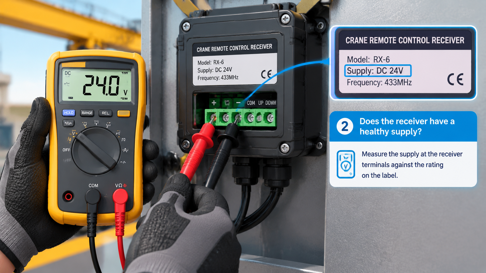
| 2. Receiver supply | Transmitter indicator normal, receiver completely silent | Blown receiver fuse, wrong supply voltage, loose terminal | Check fuse and measure the supply at the receiver terminals against the rating on the label |
| 3. Radio link | Works close to the crane but not at distance, or drops out intermittently | Lost pairing, interference, damaged or screened antenna | Re-pair, relocate the antenna, switch off other transmitters and high-power radio equipment for a test |
| 4. Receiver outputs and panel circuit | Receiver responds, one or more motions do not move | Blown output fuse, burned relay contact, contactor coil or mechanical fault | Check output fuses, test relay contacts, then check the contactor and its coil |
| 5. Machine safety devices | Nothing moves although the receiver is healthy | Travel limit, door interlock, slack rope or overload device tripped | Inspect and reset each safety device; the remote control is not at fault |
Press the start or enable button according to the normal startup sequence, then a direction button. Some transmitters signal a wrong startup sequence by flashing rapidly when a direction button is pressed without the start button. That is useful diagnostic information: if the flash pattern appears, the transmitter logic is working and you should look downstream. If nothing at all happens, treat the transmitter as the suspect.
Receivers are rated for specific voltages, so measure rather than assume. Standard receiver voltage on the F21-E1B industrial wireless remote control is AC 380 V, with AC/DC 24 V and 220 V available as options. Multi-voltage models such as the F24-10S/10D wireless remote control accept AC 36 V to 380 V or DC 12 V to 24 V, which covers most industrial supplies without an additional transformer. A receiver fed at the wrong voltage may show a power indicator and still refuse to work, so verify the label against the measurement.
Distance-dependent behaviour points at the radio path rather than the electronics. Test from three to five metres in an open area with other transmitters, access points and radio equipment switched off. If the crane responds at short range but not at working range, examine the antenna for damage and confirm where the receiver is mounted. A receiver installed inside a closed metal enclosure, or hard against a motor, cable tray or inverter, will frequently work on the bench and fail in service. Relocating the antenna and moving the receiver out of the screened enclosure often fixes a fault that looked electronic.
If the link disappears entirely, the pairing may have been lost. Re-pair the transmitter to the receiver using the routine in your documentation, and keep a record of the code or channel for each crane.
When the receiver indicators react to button presses but the motion does not move, the command has been received and the problem is downstream. Work through the panel in this order:
A good number of remote control failures are a travelling limit switch, a door interlock, a slack rope device or an overload relay doing its job. Reset the device, then investigate why it operated. Keep a spare fuse of the correct rating in the panel and the wiring diagram to hand — both make this layer far quicker than tracing by hand.
Intermittent problems rarely respond to parts swapping. Collect evidence instead. Note the crane position, the load, the time of day and which motion failed, and look for a pattern.
Some faults are safety faults, not availability faults. Take the crane out of service and have it inspected if the emergency stop does not stop every motion, if the crane makes an uncommanded movement, if the commanded direction does not match the actual movement, or if the operating distance has fallen noticeably without any change on site. Do not test these conditions with a load suspended.
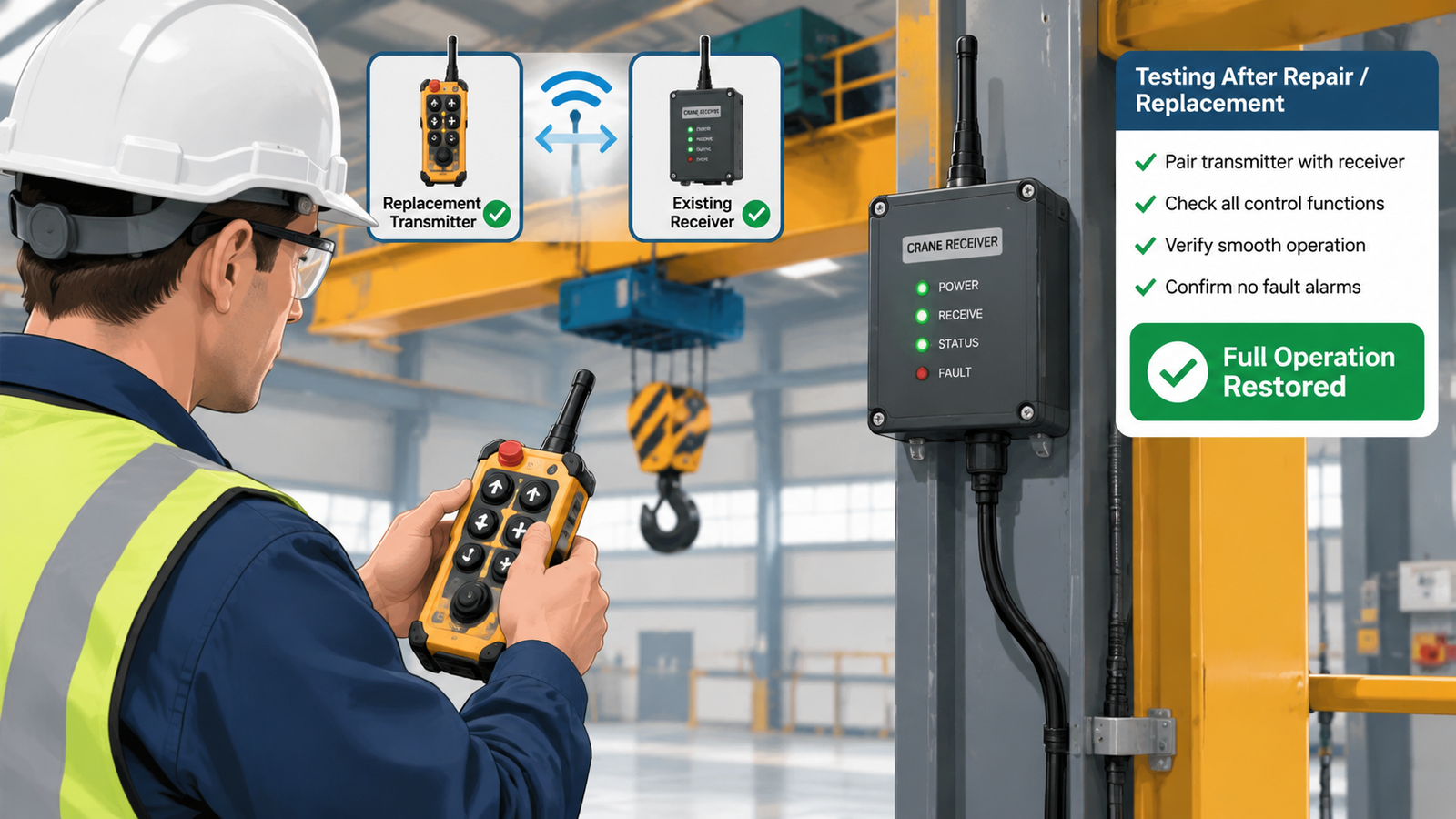
Repair is the right answer when the cause is a battery, a fuse, a re-pairing, a cable entry or a single output. Replacement makes more sense when the enclosure is cracked or water-damaged, when the antenna mounting is broken, when a relay output has burned repeatedly, or when a discontinued model can no longer be repaired with genuine parts. In those cases a compatible replacement transmitter paired to the existing receiver is usually the fastest route back into production.
Send the machine type, the receiver voltage, the current model and a description of the symptom, and we will confirm whether a repair or a compatible replacement is the better route. The product FAQ covers technical documentation, after-sales support and spare parts.
Intermittent behaviour usually indicates a marginal condition rather than a failed component: a battery below its working voltage under load, a loose terminal, an antenna partly screened at certain crane positions, or interference that comes and goes with other equipment on site.
The battery and the emergency stop. Both checks take seconds, need no tools and account for a large share of reported failures. Only move into the panel once both have been ruled out.
Yes. Strong local radio sources, other transmitters on the same channel and poorly shielded drives or welding equipment can reduce usable range or cause intermittent dropouts. Coded transmission and anti-interference design make a system more resistant, but site conditions still need assessing during commissioning.
Use a spare transmitter if one is available. If a known-good transmitter restores full operation, the original transmitter is at fault. If not, the receiver, its supply or the machine circuit is the more likely location.
The required response when the link is lost must be defined by the machine risk assessment and control-system design. Confirm that the behaviour of your system matches that requirement, and verify the emergency stop circuit independently of the radio link.