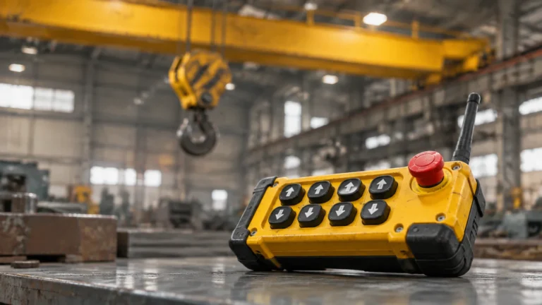
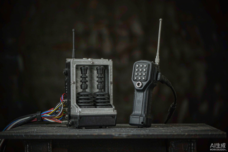
Pendant Control Station Wiring: Cores, Common, Earth
Cores follow functions, not buttons. The sum that sizes the cable, why the stop must not share the button common, and five pre-power checks.
Read More

An overhead crane remote control installation is a panel modification project with a radio link attached, not the other way round. The transmitter and receiver are the easy part to buy. What decides whether the crane is safe at handover is where the receiver is mounted, how its outputs sit in the existing contactor circuit, and whether the emergency stop path still works from every control point once the radio is added.
An overhead crane retrofit splits into five phases, and only the first is about choosing hardware.
| Phase | Work | What usually goes wrong |
|---|---|---|
| Survey | Read the existing panel, count motions, confirm control voltage and stop circuit | Quoting from the pendant button count instead of the contactor list |
| Receiver mounting | Panel or girder position, antenna orientation, cable route | Receiver buried inside a steel enclosure, range cut to a fraction of rated |
| Panel interface | Wiring transmitter outputs in parallel with pendant contactors, commoning, stop circuit | Mixing control voltages, or losing the stop function when the radio is switched off |
| Commissioning | Pairing, function test, stop test under load, range test at working positions | Skipping the stop test under load because the crane is already needed |
| Handover | Drawing update, pairing record, operator instruction | No record, so the next technician re-pairs by experiment |
The survey is where a retrofit is either priced correctly or lost. Six items should be recorded on site, with photographs, before a quotation is issued.
Two rules decide the range you actually get, and neither is in the datasheet.
Keep the antenna out of the enclosure. A receiver mounted inside a closed steel panel with the antenna coiled inside is a receiver with a fraction of its rated range. If the receiver must live in the panel, use a remote antenna brought out through a bulkhead fitting, with the cable kept short and routed away from contactor and drive cables.
Mount the antenna vertically and in the clear. Vertical polarisation matches the transmitter held in the operator’s hand, and height above the girder line helps more than any other single change. Keep it at least a hand’s width away from steelwork and away from the arc of the festoon system.
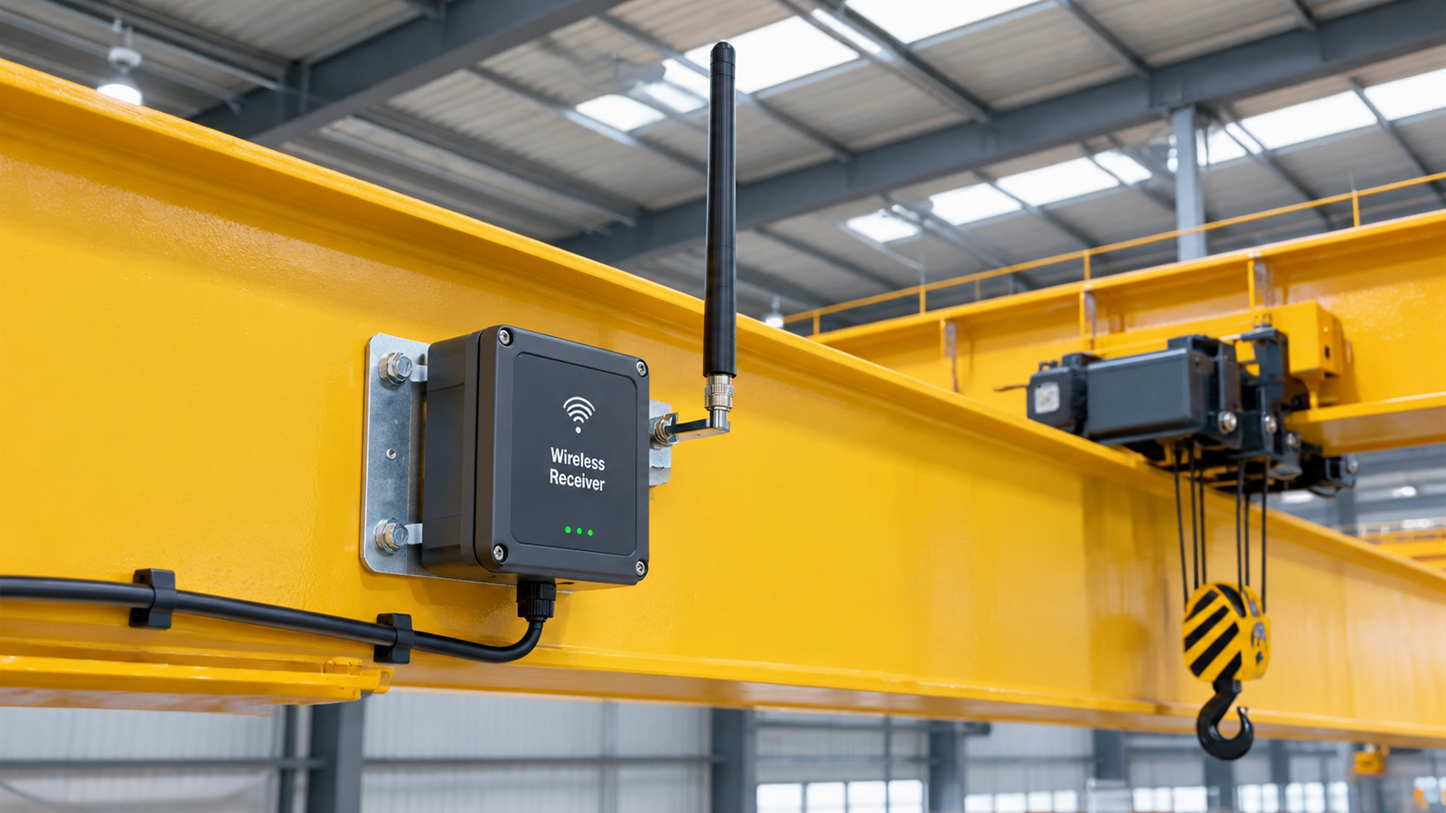
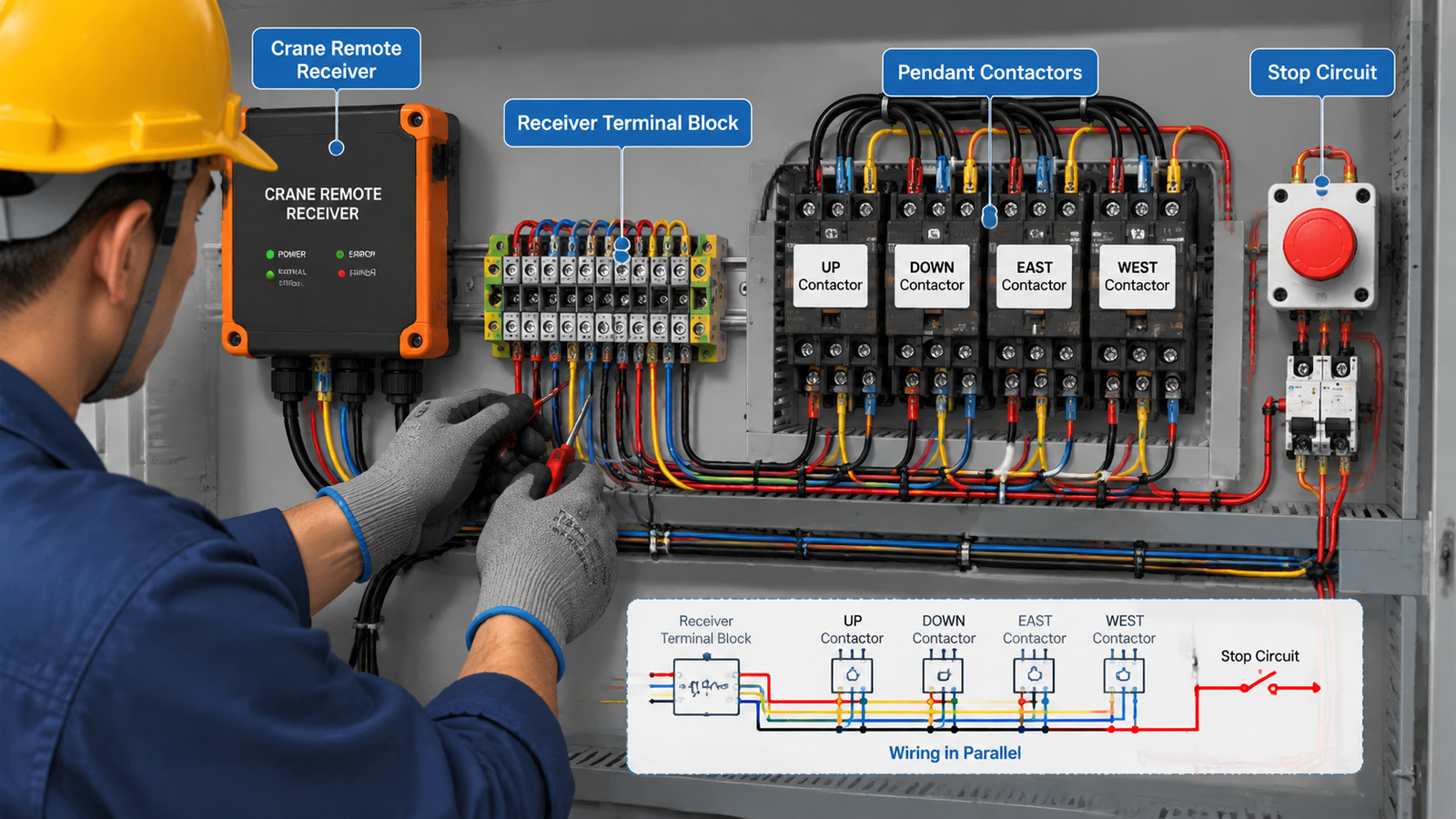
The receiver’s outputs are normally open relay contacts, and on an existing crane they are wired in parallel with the pendant contactors so that either control point can operate the machine. Three details decide whether that parallel connection is safe.
Common the right side. The receiver’s common must be the same circuit common the contactor coils use. Where a panel has more than one control voltage, the receiver must be supplied to match the circuit it commands, or the outputs must be used to drive interposing relays on the other voltage. Mixing them is the most common cause of a retrofit that works on the bench and not on the crane.
Do not put the receiver in the stop path in a way that can be defeated by removing it. If the radio system is switched off or unplugged, the pendant stop must still work, and the machine-level stop must not depend on a receiver being powered. The stop circuit is designed by the machine builder; the radio adds a stop input to it and must not replace it.
A wide-voltage receiver simplifies this section considerably. The remote control system for industrial cranes accepts AC or DC 65 V to 440 V, which removes the need for a separate control transformer on most retrofits. It carries a 32-bit ID code with Hamming error correction and an IP65 PA6 housing. The terminal detail behind that interface, including which common serves which output and why the stop pair stays separate, is drawn in the receiver wiring diagram.
Every control point must be able to stop the machine.
| Condition | Acceptable arrangement | Not acceptable |
|---|---|---|
| Pendant retained as a fallback | Pendant stop and transmitter stop both drop the machine-level stop circuit | Transmitter stop wired only to the receiver’s own output relay |
| Pendant removed | Transmitter stop drops the machine-level stop circuit; a local stop remains at the panel | No stop at the machine other than the transmitter |
| Receiver unpowered or unplugged | Pendant stop and panel stop still function | Stop function depends on the receiver being energised |
| Loss of radio link | Receiver outputs drop; the crane stops and stays stopped until re-command | Outputs hold their last state on signal loss |
Commission in a fixed order so that a failure at one step does not hide a failure at the next.
For industrial remote control transmitter selection, a dual-speed crane with three motions typically needs the twelve-channel class of unit — the F24-12S/12D covers that duty — while a single-speed hoist with one or two motions is served by a smaller station such as the F21-E1B. Choosing by motion count and speed rather than by button count avoids both under- and over-specifying.
Fit the receiver where the antenna can see the operator, wire the outputs into the circuit that already exists rather than around it, and prove the stop under load before handover. The radio link is the part that works out of the box; the installation is the part that decides whether it keeps working.
If you are quoting an overhead crane retrofit, send the motion list, control-circuit voltage, stop-circuit arrangement and a photograph of the panel through the contact form and the receiver and transmitter configuration can be confirmed before the site visit.
Physically, a single-crane retrofit is usually a day’s work for two people: survey, receiver mounting, panel wiring and commissioning. The variable is the panel — a clean panel with a spare DIN rail and labelled terminals is straightforward, while a panel with no drawing and mixed control voltages can take considerably longer.
Yes, and it is the normal arrangement on a retrofit. The receiver outputs are wired in parallel with the pendant contactors, so either control point operates the machine. Both must share the machine-level stop circuit, and both must be tested at commissioning.
Rated range is measured in clear line of sight. Steel structures, an antenna inside a closed panel, a coiled antenna, and cable routed alongside drive outputs all reduce it. Moving the antenna clear of the enclosure and above the girder line typically recovers most of the difference.
Not if it is a wide-voltage unit. Receivers that accept AC or DC 65 V to 440 V can be supplied from the existing control circuit without a transformer. Confirm the supply is taken from the same circuit the outputs command.
A correctly configured receiver drops its outputs, so the commanded motion stops and the crane does not continue on the last command. This behaviour should be demonstrated during commissioning by switching the transmitter off mid-function.