Pendant Control Station Wiring: Cores, Common, Earth
Cores follow functions, not buttons. The sum that sizes the cable, why the stop must not share the button common, and five pre-power checks.
Read More

Adding radio control to a crane that already has a pendant is a wiring job, not a rebuild. In most cases the existing contactors, overloads and limit switches stay exactly where they are, and the receiver simply takes a second path to the same coils. What decides whether the retrofit works is what you verify before ordering: control voltage, common polarity, contactor coil load, the emergency stop path, panel space and the supply you can spare for the receiver.
This guide is for maintenance engineers and crane owners who want to add radio remote control to an existing crane without replacing the control panel. It walks through the pre-order checks, the two ways the receiver can sit next to a pendant, the emergency stop question that most retrofits get wrong, and the five checks that close the job out.
A retrofit adds a receiver with output contacts that sit in parallel with the pendant’s pushbutton contacts. The pendant keeps working unless you deliberately lock it out. The main contactor, the thermal overloads, the travel limit switches and the hoist brake circuit all remain in the circuit exactly as the crane builder designed them, which is the reason a proper retrofit is far cheaper than a control upgrade.
What does change is the authority question. Before the retrofit, one pendant controlled the crane. After it, two devices can, and that has to be resolved by procedure or by wiring.
Every one of these has a wrong answer that only shows up after the receiver is on the panel. A photo of the panel interior, the control transformer nameplate and the pendant’s terminal markings usually answer all six in a single email.
| Check | What to record | Why it matters |
|---|---|---|
| Control voltage | Measured AC or DC volts at the contactor coils | The receiver must match it; a mismatch means a transformer or a different unit |
| Common polarity | Whether the pendant switches the live or the neutral side | Decides the common terminal arrangement of the output contacts |
| Contactor coil load | Coil rating and how many coils operate at once | Overload on one output pair is the most common retrofit failure |
| Emergency stop path | How the pendant stop button drops the main contactor | Determines where the receiver’s stop relay has to sit |
| Panel space | Free area and depth on the mounting plate | A receiver is a box, not a terminal strip |
| Supply capacity | Spare VA on the control transformer | The receiver draws continuously, not only when a button is pressed |
Measure the control voltage with a meter rather than trusting a nameplate that may have been changed twice since commissioning, and check spare transformer capacity, because a receiver running close to the limit will sag the control circuit when contactors pick up. Hoist-side retrofits differ from a crane-wide one in scope rather than in method, and converting a chain hoist to radio control is the smaller version of the same job.
Mount the receiver on the panel plate where its antenna can be routed straight up and out through a gland on the enclosure top, ideally to a bracket above the girder line. Keep the antenna lead away from contactor coils, variable frequency drives and the hoist motor cables. A receiver buried at the bottom of a steel cabinet behind a row of contactors will pass its bench test and fail in service, because the panel itself becomes the obstruction.

If depth is tight, a compact receiver mounted on the outside face of the panel with a short glanded cable run is a legitimate answer and often a better one thermally. Leave the receiver’s own diagnostic indicators visible, because the first question during commissioning and during every future fault will be whether the unit is receiving. The isolator is the other part that often changes at the same time, and the LW26GS rotary isolator switch is sized by the panel current rather than by the crane rating.
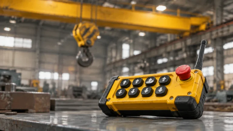
Each receiver output pair is a dry contact. Wire it across the matching pendant contact — output one across the pendant’s up button contact, output two across down, and so on — so that either device can complete the same circuit. This is the standard approach and it is what a complete crane remote control system is designed to do.
Parallel wiring means the crane responds to whichever device is pressed, including when two people press at once. If your site cannot accept that, either park and lock the pendant at the start of every radio shift, or specify a unit with a changeover key so only one authority is live. A plain F24-8S 8D style eight-function unit is the usual starting point for single-speed crane motions; two-speed motions need double the output pairs for the same three motions. The full sequence from survey to handover, including where the receiver and antenna physically go, is set out in the integrator walk-through of an overhead crane retrofit.
This is the part where a retrofit can go wrong in a way nobody notices until an incident. The transmitter’s stop button must be able to drop the crane, and it has to do so through the existing safety path rather than through a circuit that only the receiver knows about.
Approach one: series into the existing stop chain. The receiver’s stop relay contact is wired in series with the pendant stop contact and the other devices that already hold the main contactor in. Pressing either stop button opens the same chain. This keeps one safety path and one thing for a fault-finding technician to understand.
Approach two: a dedicated safety relay. Both the pendant stop and the receiver stop feed a dual-channel safety relay that drops the contactor. This is more hardware and more wiring, but it gives monitored channels and it is the shape most machine risk assessments expect when two control stations exist.
Which one your crane needs is a decision for the machine’s risk assessment and the standards that apply on your site, not something a supplier should settle for you. What a supplier absolutely must not do is offer a receiver whose stop output only interrupts the receiver’s own outputs while the main contactor stays held in by another device. Wire the output contacts so a receiver failure cannot bypass a limit switch either; limit switches protect the machine, and remote control is not their replacement.

Travel limits belong in the same commissioning pass even though they sit outside the radio system, and choosing the actuator and contact arrangement for a travel limit is what decides whether the stop is repeatable. Where the retrofit renews panel hardware rather than only adding a receiver, the isolators, changeover switches and pedals are listed in the control switch range.
Commission with the crane unloaded, and treat the order as fixed because each check depends on the one before it.
Check your control voltage before ordering with the control voltage selection guide, because voltage is the single item that most often turns a planned retrofit into a second order. And if the crane currently runs on a pendant that operators already dislike, compare the two control methods properly before deciding how much of the job to do at once — the pendant versus radio comparison covers when a retrofit is genuinely the right spend.
Yes, and most retrofits do. The receiver’s dry contacts sit in parallel with the pendant contacts, so both devices can command the same motion. The pendant should be parked and locked out during radio shifts so only one operator commands the crane at a time.
You need more output pairs, not a different technology. A single-speed hoist, trolley and bridge need six pairs; the same three motions in two speed need twelve. Confirm the motion count from the panel drawing before choosing a model.
A correctly configured receiver drops its outputs when the signal disappears, so the motion stops rather than continues. Test this deliberately during commissioning by removing the battery with a motion running, and make sure the load is held by the brake, not by the remote control.
Usually, if there is spare capacity and the transformer secondary matches the receiver’s rated voltage. Check the spare volt-amperes rather than the rated output, because a transformer running close to its limit will sag when contactors pick up.
The party responsible for the crane’s risk assessment, working from the existing safety circuit. The supplier’s job is to state clearly what the receiver’s stop output does and does not interrupt, and to supply the terminal data needed to wire it into the correct path. Send your panel details through the contact page and ask for the stop arrangement to be confirmed in writing before shipment.