Pendant Control Station Wiring: Cores, Common, Earth
Cores follow functions, not buttons. The sum that sizes the cable, why the stop must not share the button common, and five pre-power checks.
Read More

To test a crane remote control receiver, isolate it from the crane first, then feed it from a bench supply and prove each output with a substitute load rather than the machine. The order matters more than the instrument: confirm the transmitter is sending, then confirm the receiver is decoding, then confirm each output switches. Skipping straight to the relay gets most people to the wrong part.
Three different failures look identical from the cab: nothing moves. Before anything is unbolted, separate them with what is already in front of you.
Watch the receiver’s own indicators while the operator presses a button. A receiver that shows a valid signal and a lit output is telling you the fault is downstream, in the contactor or the machine. Signal but no output is a receiver or configuration fault. No signal at all points at the transmitter, the pairing or the radio path, which on a crane usually means antenna, battery or new interference. The symptom tree in crane remote control not working covers the field side; this procedure starts after that has been eliminated.
One test settles the transmitter question in under a minute. Pair a known-good transmitter to the receiver, or take the suspect transmitter to a second crane on the same frequency plan. If the fault follows the transmitter, stop: the bench work below will only confirm what you already know.
A receiver is not tested safely while it is connected to a live panel with a hoist on the hook. Take it off the crane, or open the control circuit and lock it out, then work from a bench supply of the correct voltage. A 24 V AC receiver will not survive 24 V AC plus charger ripple, and a 48 V AC unit fed 24 V DC will behave in ways that have nothing to do with its real condition.
The load matters too. Do not test outputs with a multimeter alone: a digital meter draws microamps, so it shows a healthy 24 V on a contact that cannot carry a relay coil, and nothing on a solid-state output that leaks. Use a load of roughly the same coil current as the contactor.
| Item | What it is for | Common mistake |
|---|---|---|
| Bench supply at the panel voltage | Powering the receiver off the machine | Reusing a 12 V charger for a 24 V receiver |
| Four to six 24 V relay coils or a test lamp bank | Loading each output enough to prove it | Testing with a meter only, missing a dry contact |
| Multimeter with continuity | Checking common, fuse and output state | Measuring voltage on an open contact and calling it dead |
| Small insulated screwdriver | Terminal screws, DIP switches | Adjusting a DIP switch without recording the original position |
| Test record sheet | Comparing channels between visits | Testing from memory, then repeating the same work |
Photograph the terminal block and the DIP switch positions before touching anything. Half the receivers returned as faulty come back with a configuration that no longer matches the crane.
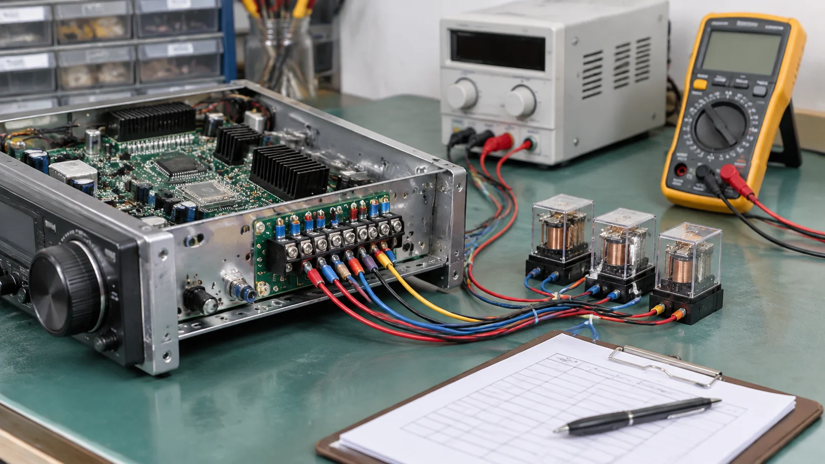
Test in a fixed order every time, so a result can be compared with the previous visit. The order below follows the way the crane is actually driven, which makes an interlock fault obvious.
Record pass or fail per channel as you go. One failed channel with everything else healthy is a component problem; a block of failures in sequence usually means a common terminal or a configuration error.
Most receiver faults are reported as “the contact is dead” when the contact is behaving exactly as designed. Normally-open and normally-closed outputs read in opposite ways, and a receiver may use either for the same function depending on the crane’s safety philosophy.
| Contact type | Idle reading | Energised reading | What a wrong reading means |
|---|---|---|---|
| Normally open (NO) | Open circuit | Closed, load lamp lit | Closed at idle: welded contact or wrong configuration |
| Normally closed (NC) | Closed circuit | Open | Open at idle: coil faulty or circuit broken elsewhere |
| Changeover (CO) | Common to NC | Common to NO | Both closed or both open: mechanical failure inside the relay |
Check the wiring diagram before condemning an output. A channel that reads open at idle is correct if the drawing says NO and the function only energises on command. Terminal numbering on the crane remote control wiring diagram follows the pendant it replaced, which matters when a crane was converted and the panel was never renumbered.
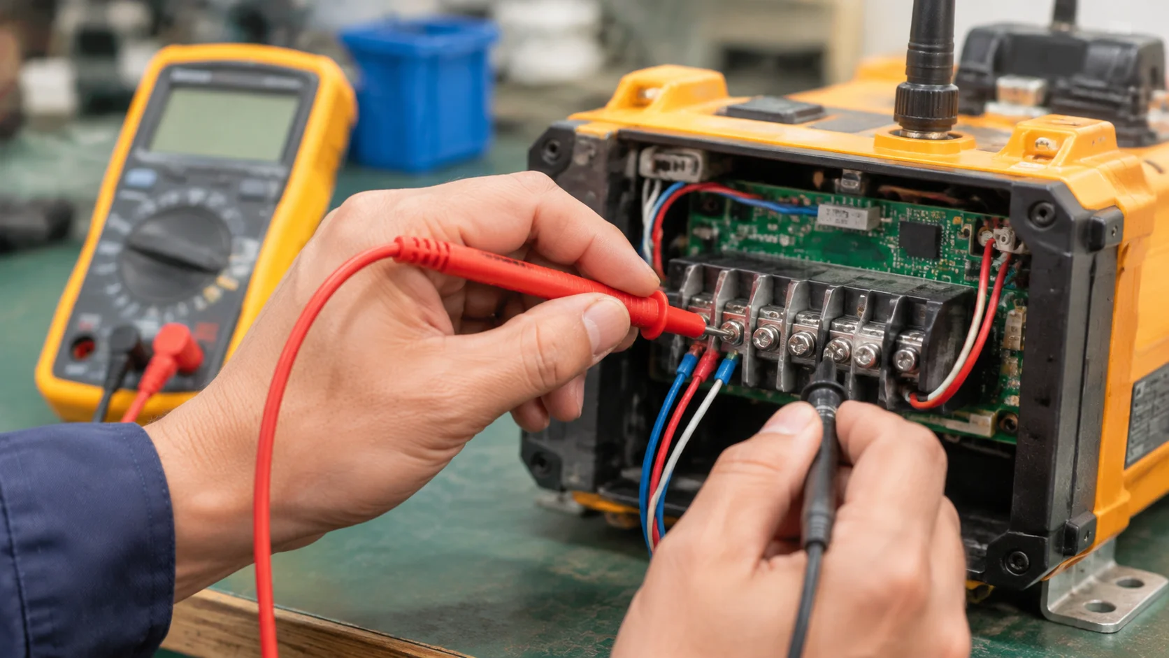
Once an output fails, three causes cover almost everything, and each has a distinct signature on the bench.
A welded relay reads closed at idle with no command given, and stays closed when the transmitter is switched off. It is the most dangerous of the three because the crane keeps a motion enabled. Replace the relay and then find out why it welded: a contactor coil with a shorted turn, an undersized contact, or a two-speed changeover that closes both directions together.
A dead output reads correctly at idle but never changes state on command, while the receiver indicator shows the command arriving. That is a driver or relay coil failure on that channel, not a radio or pairing problem.
A bad command looks like a dead output but moves around: the same button works on one press and not the next, or works only when the transmitter is close. Check the pairing and the button itself before opening the receiver. A worn keypad contact that makes intermittently is far more common than a receiver fault, and it is the case most often misdiagnosed as “the receiver is going”.
The electrical difference between relay and solid-state outputs matters here, because the bench test differs: a solid-state output may show a small leakage voltage when off, which a meter reads as a fault and a load correctly ignores. Receiver output: relay versus solid state explains which readings are normal for each type.
Repair is the cheaper answer when the fault is one identifiable component, the housing and seals are sound, and the receiver is still in production. Replace when any of the following is true: the enclosure has cracked or the gasket has hardened, the terminal block or PCB shows corrosion from water ingress, more than one channel has failed, or the model is obsolete and spares are no longer available.
A repair that leaves a corroded board in a wet housing will be back within a season. Replacing a receiver because one contactor coil was shorted also wastes a working unit; the new one will fail the same way. On a standard crane, a current eight-function wireless remote control is often cheaper than a board-level repair, and a full industrial crane remote control system makes sense when the panel is rebuilt at the same time.
Keep the test record with the crane, not with the technician. Two readings a year apart show whether a channel is drifting, and that evidence turns a recurring fault into a planned replacement. Send the readings with the model and supply voltage through the contact form and a replacement can be quoted against the actual failure.
Only by opening and locking out the control circuit. Testing with the panel live and a hoist attached risks a motion during the test, and the substitute load cannot be connected safely. Take the receiver off, or test with the motor circuits isolated.
A digital meter draws almost no current, so it reads a healthy voltage through a high-resistance path or a leaking solid-state output. Load the output with a relay coil or test lamp and measure again before calling the output faulty.
The contact stays closed with no command, and stays closed with the transmitter switched off. Confirm with the load connected and the receiver powered; a meter alone can be misleading on a contact that is still passing leakage current.
No. A single failed channel on an otherwise healthy receiver with sound seals is usually a replaceable relay or driver. Replace the unit when several channels have failed or the housing and terminals show water damage.